Communication connector with analog coupling circuit

a technology of communication connector and analog coupling circuit, which is applied in the direction of coupling device connection, contact, electric discharge lamp, etc., can solve the problems of lack of security devices, added weight, and clunky feel of electronic devices

Active Publication Date: 2013-08-27
VANGUARD PRODS GROUP
View PDF39 Cites 26 Cited by
  • Summary
  • Abstract
  • Description
  • Claims
  • Application Information

AI Technical Summary

Benefits of technology

[0012]The novel invention may further include a shroud device used to secure the male USB to an electronic device. Shroud comprises a first arm and a second arm being disposed in perpendicular relation to one another connected by an elbow joint. First arm includes an adhesive side and a base side. Adhesive side of the first arm includes a mechanism for attaching firm arm to an electronic device. A gap is formed within the second arm and first arm extending through the elbow joint. Gap allows for a male USB to engage the device without being removed when the male USB is in a horizontal orientation.

Problems solved by technology

This poses a problem with the evolution of technology.
This creates a problem in retail stores that want to show the technology of the phone, but are prevented from doing so because of a security device attached to the back of the cellular phone.
Presently, there is a lack of security devices that will alarm against potential theft while leaving the back of the cellular phone substantially free.
Additionally, many security devices in the prior art substitute aesthetics for security of the electronic device.
The large, clunky security devices attached to the back of many cellular phones add weight and a clunky feel to the electronic device.

Method used


Image

  • Communication connector with analog coupling circuit
  • Communication connector with analog coupling circuit
  • Communication connector with analog coupling circuit

Examples


Embodiment Construction

[0021]In the following detailed description of the preferred embodiment, reference is made to the accompanying drawings, which form a part hereof, and within which are shown by way of illustration specific embodiments by which the invention may be practiced. It is to be understood that other embodiments may be utilized and structural changes may be made without departing from the scope of the invention.

[0022]As used in this specification and the appended claims, the singular forms “a”, “an”, and “the” include plural referents unless the content clearly dictates otherwise. As used in this specification and the appended claims, the term “or” is generally employed in its sense including “and / or” unless the context clearly dictates otherwise.

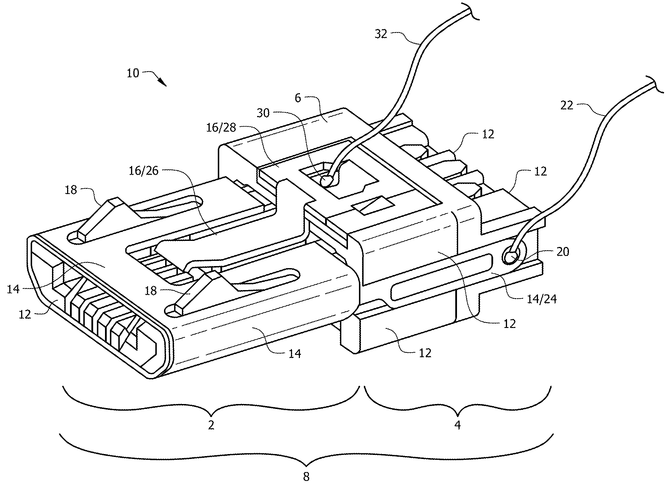
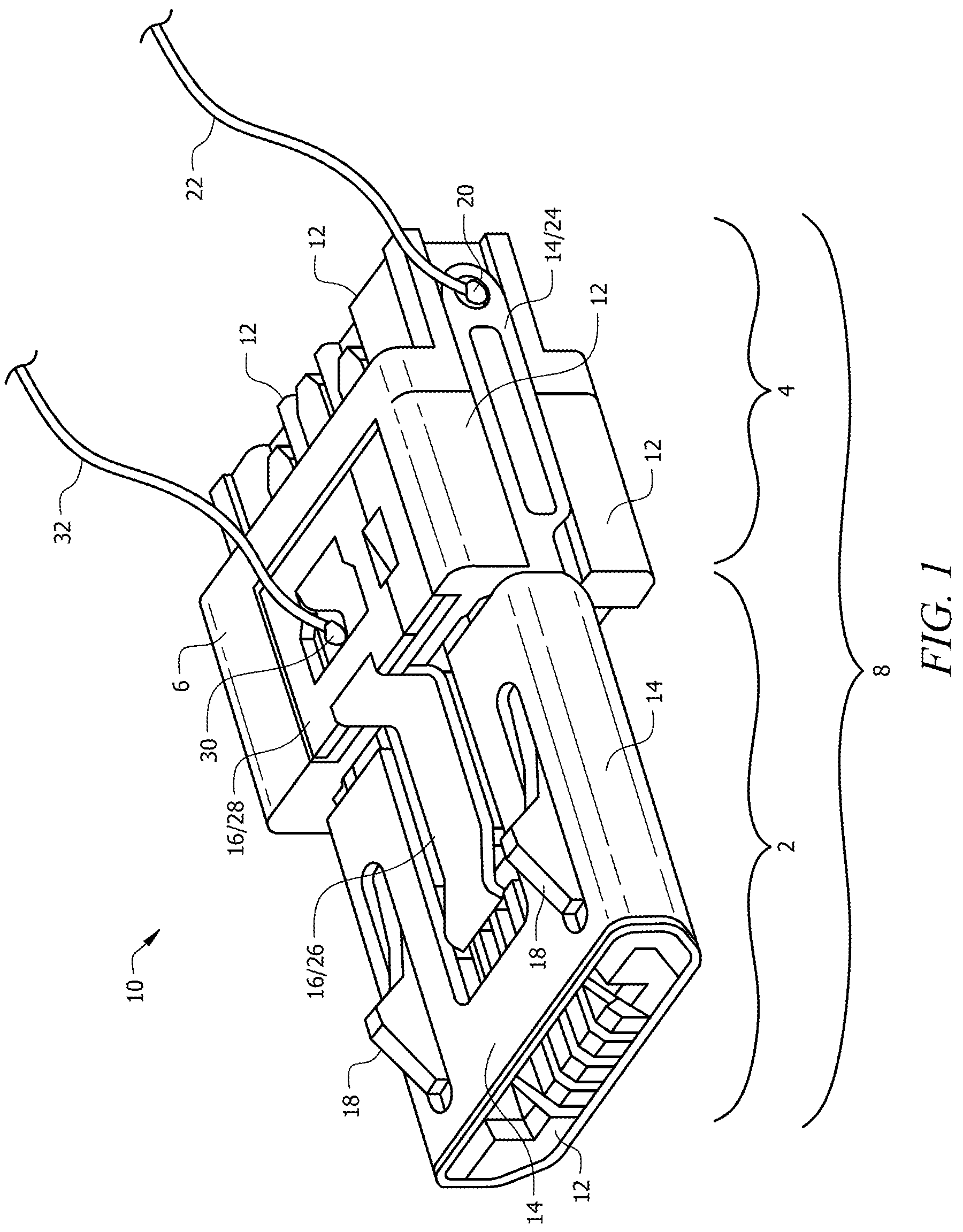
[0023]The novel structure is denoted as a whole in FIG. 1 by the reference numeral 10. FIG. 1 depicts a view of a male USB connection portion in accordance with a preferred embodiment of the present invention. A first shell 12 substantially forms a ...


PUM


Abstract

A communication connector with analog coupling circuit and a mechanical coupling circuit used for providing security to electronic devices. The analog circuit includes a male plug with an outer shell and tongue shell. Between the outer shell and tongue is a thin layer of non-conductive material to prevent the closure of a circuit. Two separate conductors are wired through the USB body; one attaching to the outer shell and the other attaching to the tongue. A closed circuit is created when the male USB is placed into a female receptor. The mechanical circuit creates a closed circuit when the plunger switch becomes compressed. There is a security monitor system connected to an end of the two conductors, which sound an alarm when circuit is opened. The alarm will sound if a thief attempts to steal the article either by cutting the wire or removal of the plug.

Description

CROSS-REFERENCE TO RELATED APPLICATIONS[0001]This non-provisional application is a continuation of and claims priority to provisional application No. 61 / 674,629 entitled “COMMUNICATION CONNECTOR WITH ANALOG COUPLING CIRCUIT,” filed Jul. 23, 2012.BACKGROUND OF THE INVENTION[0002]1. Field of the Invention[0003]This invention relates to electronic device security through an analog electrical circuit. More specifically, it relates to an alarm system created through a closed circuit in the single point of entry for an electronic charging plug, such as a micro USB (Universal Serial Bus).[0004]2. Brief Description of the Related Art[0005]Currently, electronic devices are secured in stores through various locking mechanisms. Some of these mechanisms are equipped with an alarm to warn when the device is unplugged. Many of the devices meant to protect against theft of the electronic device impede the consumer from fully accessing and utilizing the device. One of the most common examples of se...

Claims


Application Information

Patent Timeline
Patent Type & Authority Patents(United States)
IPC IPC(8): H01R29/00H01H1/58
CPCH01R13/6397H01H1/5866H01R13/665H01R13/7032H01R13/7175
Inventor KELSCH, CHRISTOPHER A.LEE, CHUNG-PINGFIGH, JR., JOHN N.SWARTWOOD, LUCAS P.TELLES, BRUNO M. L.
Owner VANGUARD PRODS GROUP
Why Eureka
Try Eureka