Method and system for providing a laser cavity for an energy assisted magnetic recording head

a technology of energy assisted magnetic recording and laser cavity, which is applied in the field of methods, can solve the problems of reducing the size of the laser, adversely affecting the reliability of the conventional eamr disk drive, and less reliable lasers

Active Publication Date: 2013-08-27
WESTERN DIGITAL TECH INC
View PDF12 Cites 148 Cited by
  • Summary
  • Abstract
  • Description
  • Claims
  • Application Information

AI Technical Summary

Problems solved by technology

Although smaller lasers 30 might be used, such lasers are typically less reliable.
Consequently, reducing the size of the laser 30 may adversely affect reliability of the conventional EAMR disk drive 10.

Method used


Image

  • Method and system for providing a laser cavity for an energy assisted magnetic recording head
  • Method and system for providing a laser cavity for an energy assisted magnetic recording head
  • Method and system for providing a laser cavity for an energy assisted magnetic recording head

Examples


Embodiment Construction

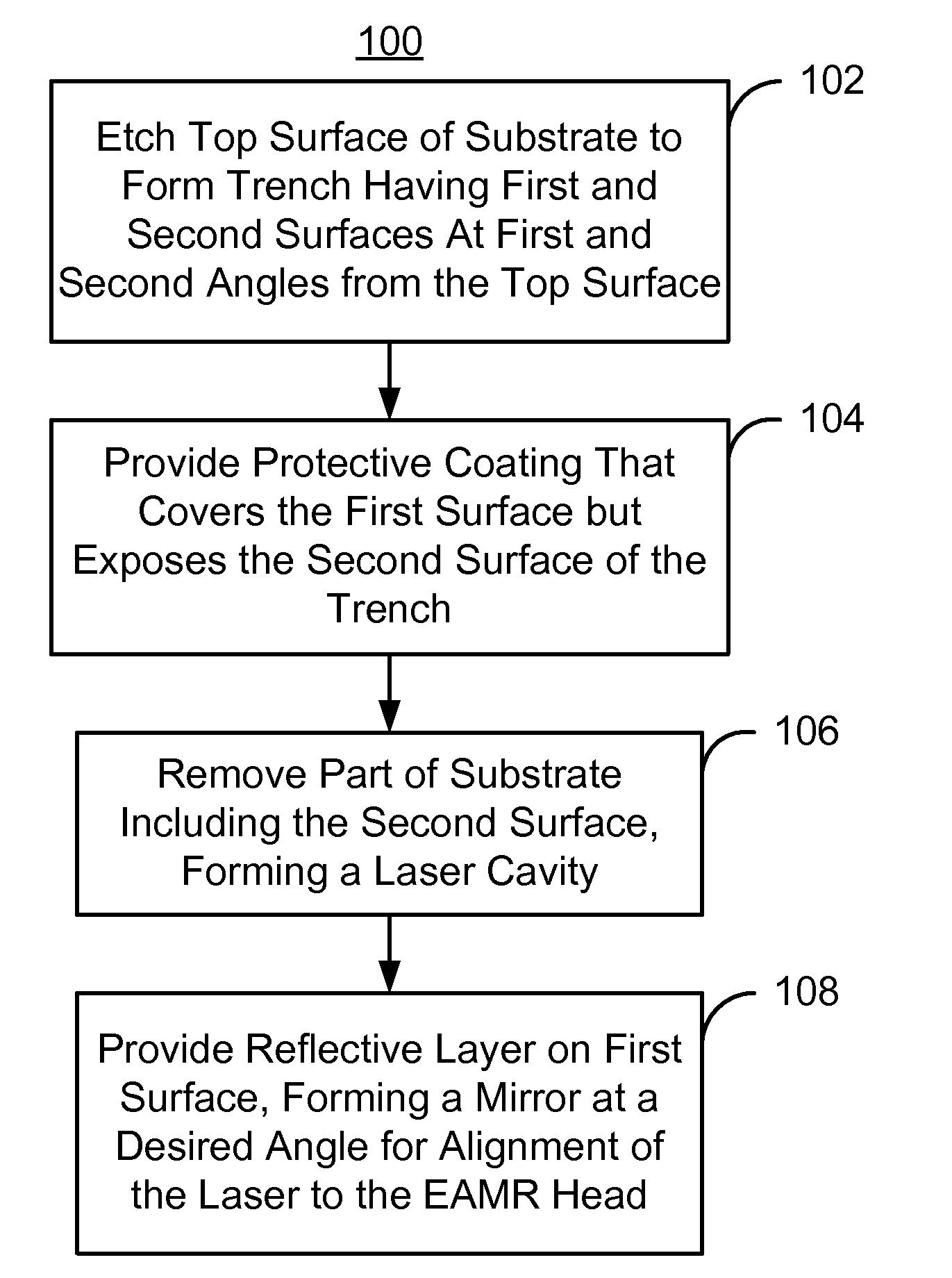
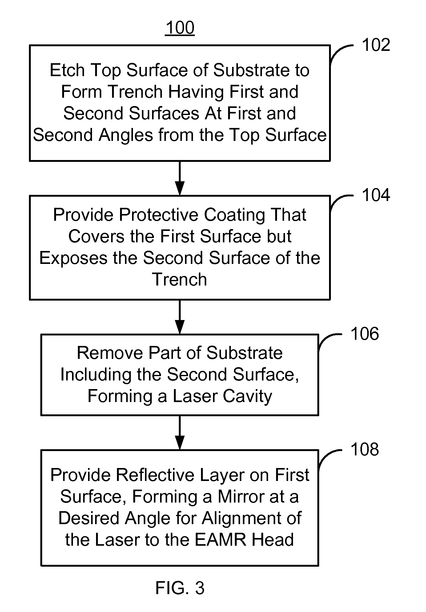
[0015]FIG. 3 is a flow chart depicting an exemplary embodiment of a method 100 for fabricating capping layers that may be used in conjunction with EAMR heads. Although certain steps are shown, some steps may be omitted, interleaved, performed in another order, and / or combined. The EAMR heads may be merged heads, each of which includes an EAMR write transducer, a read transducer (not shown) and resides on a slider. Further, the capping layers being fabricated may be used in other applications in which alignment of lasers is desired.

[0016]A substrate having a top surface is etched, via step 102. The etch forms a trench in the substrate. The trench has a first surface at a first angle from the top surface and a second surface having a second angle from the top surface. In some embodiments, the trench formed has the shape of a “v”. However, in other embodiments, the trench may have another shape. The first angle is a desired angle for alignment to the EAMR head. In some embodiments, the...


PUM

PropertyMeasurementUnit
angleaaaaaaaaaa
re-entrant angleaaaaaaaaaa

Abstract

A method for providing a capping layer configured for an energy assisted magnetic recording (EAMR) head including at least one slider. The method comprises etching a substrate having a top surface using an etch to form a trench in the substrate, the trench having a first surface at a first angle from the top surface and a second surface having a second angle from the top surface. The method further comprises providing a protective coating exposing the second surface and covering the first surface, removing a portion of the substrate including the second surface to form a laser cavity within the substrate configured to fit a laser therein, and providing a reflective layer on the first surface to form a mirror, the cavity and mirror being configured for alignment of the laser to the laser cavity and to the mirror and for bonding the laser to the laser cavity.

Description

BACKGROUND[0001]FIG. 1 depicts a side view of portion of a conventional energy assisted magnetic recording (EAMR) disk drive 10. The conventional EAMR disk drive 10 includes a recording media 12, a conventional slider 20, and a conventional laser diode 30 that are typically attached to a suspension (not shown). The conventional slider 20 has a leading edge 22, a trailing edge 26, and a back side 24. Although termed “edges”, the leading edge 22 and trailing edge 26 are surfaces of the slider 20. The leading edge 22 and trailing edge 26 are so termed because of the direction the conventional media 12 travels with respect to the EAMR transducer 28. Other components that may be part of the conventional EAMR disk drive 10 are not shown. The conventional slider 20 is typically attached to the suspension at its back side 24. A conventional EAMR transducer 22 is coupled with the slider 20.[0002]The laser diode 30 is coupled in proximity to the EAMR transducer 22 on the trailing edge 26 of t...

Claims


Application Information

Patent Timeline
Patent Type & Authority Patents(United States)
IPC IPC(8): B29D11/00
CPCG11B5/3163G11B5/105H01L43/12G11B5/102Y10T428/1193G11B2005/0021Y10T29/49032H10N50/01
Inventor WANG, LEIMONADGEMI, PEZHMAN
Owner WESTERN DIGITAL TECH INC
Why Eureka
Try Eureka