Position and orientation measurement apparatus and method thereof

a technology measurement apparatus, which is applied in the field of position and orientation measurement apparatus and method, can solve the problems of difficult to describe the off-line three-dimensional line segment model of the edge based on the contour formed by the curved surface, the inability to accurately estimate the position and orientation of the imaging apparatus, and the inability to accurately estimate the position and orientation. , to achieve the effect of stabilizing and improving the position and orientation detecting processing and stably estimating the position

Active Publication Date: 2013-08-27
CANON KK
View PDF15 Cites 112 Cited by
  • Summary
  • Abstract
  • Description
  • Claims
  • Application Information

AI Technical Summary

Benefits of technology

[0040]The present invention is directed to a position and orientation measurement apparatus which can stabilize and improve position and orientation detecting processing by appropriately selecting features which are used for calculating a position and orientation from among features extracted from three-dimensional model data of an observation object. Further, the present invention is directed to a position and orientation measurement apparatus which can stably estimate the position and orientation even when the feature extracted from the three-dimensional model data of the observation object is greatly different from the feature which can be extracted from the observation object captured into the captured image.

Problems solved by technology

If many edges which cannot be recognized as the three-dimensional line segment model are detected from the captured image, wrong points can be detected as the corresponding points, thus resulting in erroneous correspondence.
Thus, the accuracy of the position and orientation of the imaging apparatus may be deteriorated.
However, selecting and manually generating the three-dimensional edge which is to be observed from the actual observation object are comparatively complicated and highly time consuming.
Furthermore, the edge based on a contour formed by a curved surface is hard to be described as the off-line three-dimensional line segment model.
However, there is a problem in which the method described above cannot be applied for such a case where a previously-drawn appearance of the observation object and an on-line appearance thereof are not always the same, for example, where an object having a curved surface is viewed from various directions.
However, there is no guarantee for the method for generating the three-dimensional line segment model by previously drawing the three-dimensional model data off line that the feature corresponding to the generated three-dimensional line segment model is always detected from the captured image.
When the feature corresponding to the generated three-dimensional line segment model cannot be detected from the captured image, the line segment is highly likely to cause the erroneous correspondence.
Thus, the accuracy for estimating the position and orientation can be deteriorated.
Further, since the method discussed in Literature 5 previously draws the three-dimensional model and generates the three-dimensional line segment model from a depth value of the drawn image, the feature corresponding to the generated three-dimensional line segment model cannot be always detected from the actual captured image.
Therefore, if there are plenty of features to be eliminated as erroneous correspondence, for example, if the three-dimensional line segment model itself is inaccurate, the position and orientation cannot be stably estimated.
Thus, even if the method of Literature 4 is used, the position and orientation is not stably estimated when the three-dimensional line segment model is inaccurate.
On the contrary, the feature can cause the erroneous correspondence.
Thus, if the appearance of the three-dimensional model data is different from that of the actual observation object, for example when the setting of the three-dimensional model data is inaccurate, or a light source changes in an actual environment, the generated three-dimensional line segment model is inaccurate.
However, when the actual environment changes, there is no method for dealing with the problem.
Accordingly, when the three-dimensional line segment model is inaccurate, similarly to the above-described method, the erroneous correspondence frequently occurs between the three-dimensional line segment data and the edge in the captured image.
Thus, the position and orientation cannot be stably estimated.
Further, the method for estimating the position and orientation by generating the three-dimensional line segment model from only the captured image as discussed in Literature 7 does not have enough accuracy for estimating the position and orientation.
That is because the accuracy of the three-dimensional line segment model is deteriorated compared to the method for generating the three-dimensional line segment model using the three-dimensional model data.

Method used


Image

  • Position and orientation measurement apparatus and method thereof
  • Position and orientation measurement apparatus and method thereof
  • Position and orientation measurement apparatus and method thereof

Examples


Embodiment Construction

[0063]Various exemplary embodiments, features, and aspects of the invention will be described in detail below with reference to the drawings.

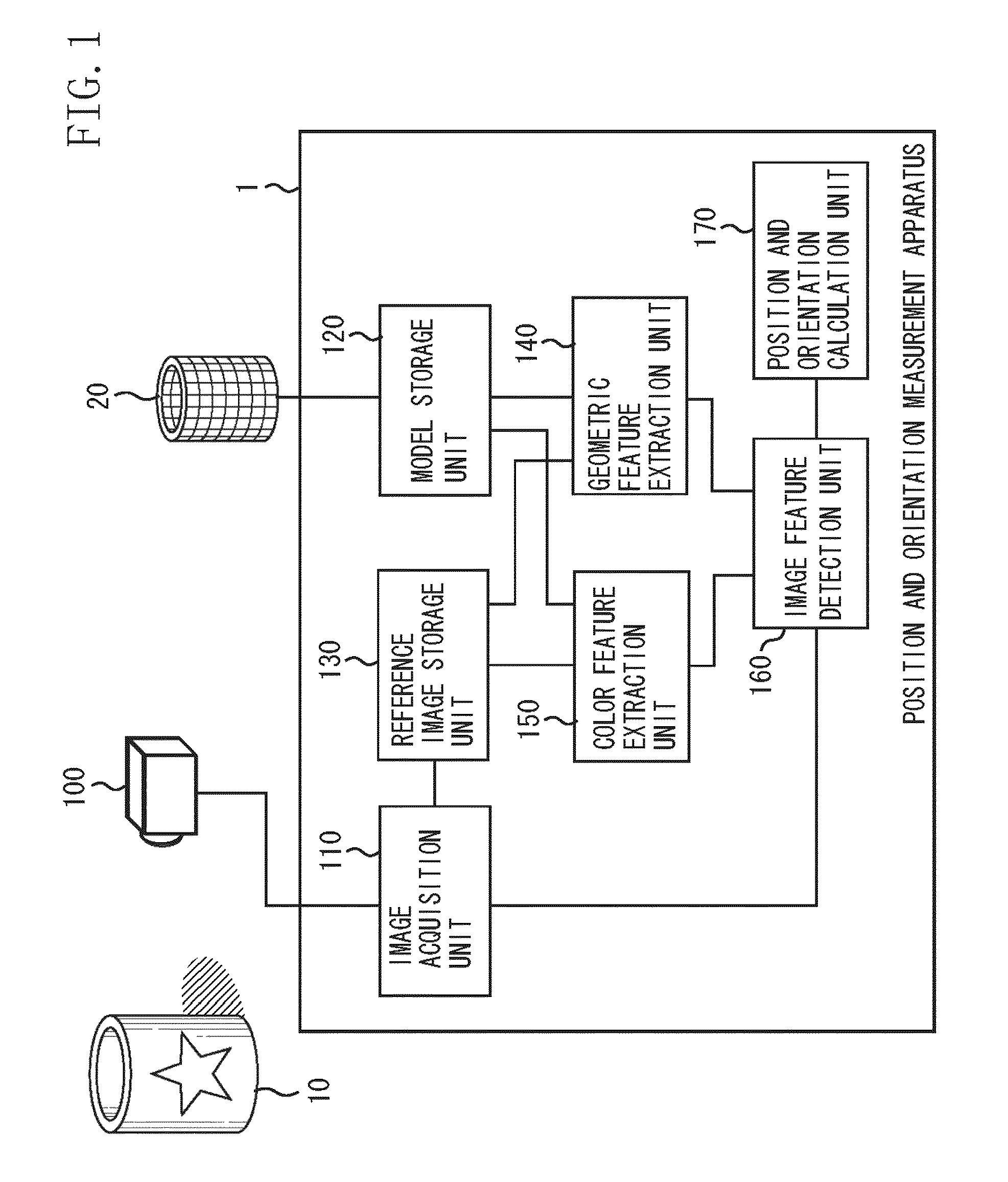
[0064]FIG. 1 illustrates a functional configuration of a position and orientation measurement apparatus 1 according to a first exemplary embodiment of the present invention. The position and orientation measurement apparatus 1 can be implemented by, for example, allowing a general computer apparatus to perform software for realizing a function which will be described below. In this case, a part or all of functional configurations which will be described below is to be performed by a central processing unit (CPU) of the computer apparatus. Second and third exemplary embodiments can be implemented similarly to the first exemplary embodiment.

[0065]As illustrated in FIG. 1, the position and orientation measurement apparatus 1 includes an image acquisition unit 110, a model storage unit 120, a reference image storage unit 130, a geometric feature ex...


PUM


Abstract

A position and orientation measurement apparatus extracts a plurality of geometric feature based on geometric information of an observation object by drawing three-dimensional model data which represents a surface shape of the observation object. Further, the position and orientation measurement apparatus searches an image feature corresponding to the plurality of geometric feature in a reference image in which a position and orientation of an imaging apparatus relative to the observation object has been calculated and selects the geometric feature whose corresponding image feature is detected from the plurality of extracted geometric features. The position and orientation measurement apparatus calculates the position and orientation of the imaging apparatus relative to the observation object by associating the selected geometric feature with an image of the observation object in an input image.

Description

BACKGROUND OF THE INVENTION[0001]1. Field of the Invention[0002]The present invention relates to a position and orientation measurement apparatus and method thereof which measure a position and orientation of an imaging apparatus relative to an observation object, the measurement using an image of the observation object captured by the imaging apparatus and three-dimensional model data which represents a surface shape of the observation object.[0003]2. Description of the Related Art[0004]A conventional technique has been discussed in which a relative position and orientation of an imaging apparatus which captures the observation object relative to an observation object is measured by the imaging apparatus such as a camera which captures a real space. Such a position and orientation measurement technique is considerably beneficial for a mixed reality system which integrates and displays the real space and a virtual space, and also for measurement of the position and orientation of a ...

Claims


Application Information

Patent Timeline
Patent Type & Authority Patents(United States)
IPC IPC(8): G06K9/00G01B11/00G01B11/24G01B11/26G06F3/038G06T1/00G06T7/60G06T15/00G06T19/00
CPCG06K9/00208G06K9/6204G06V20/647G06V10/752
Inventor TATENO, KEISUKE
Owner CANON KK
Why Eureka
Try Eureka