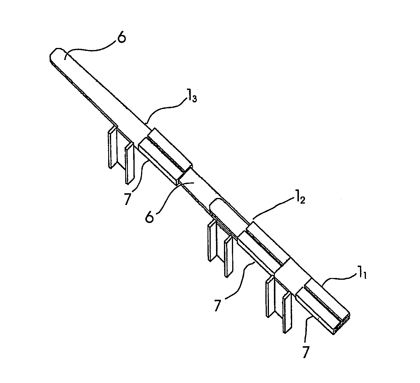
Sternum reinforcing device to be used after a sternotomy or a sternal fracture
a technology of sternotomy and sternal fracture, which is applied in the field of sternum reinforcing device to be used after sternotomy or sternal fracture, can solve the problems of wire breaking, infection and mediastinitis risk, and the current method of medial sternotomy is not free of complications, and achieves the effect of high risk of damag
- Summary
- Abstract
- Description
- Claims
- Application Information
AI Technical Summary
Benefits of technology
Problems solved by technology
Method used
Image
Examples
first embodiment
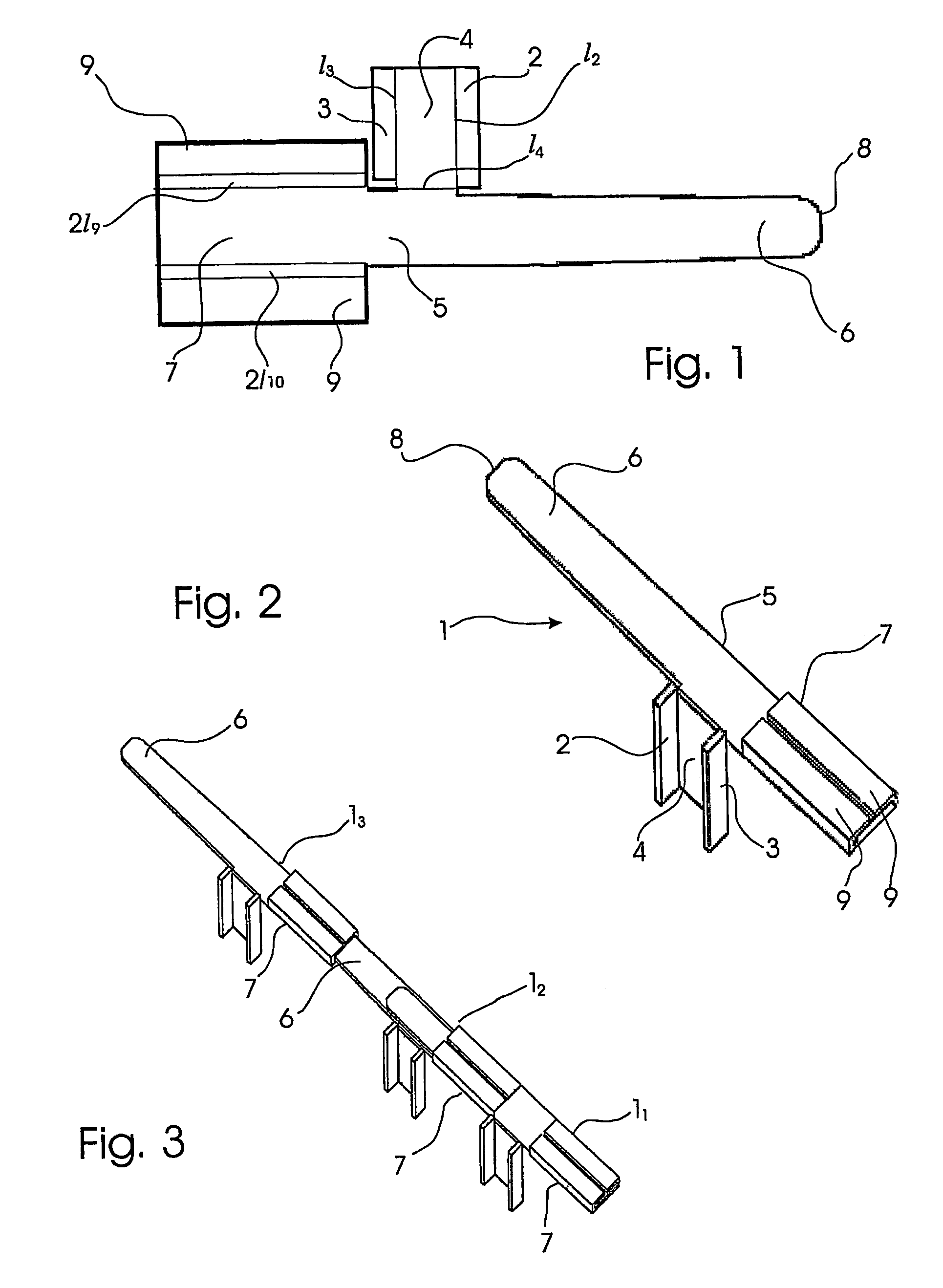
[0025]With reference to the drawings, shown in the plan view of FIG. 1 is the device according to the present invention in a semifinished condition, i.e. in the form of a punched plate blank (totally lying in the plane of the drawing sheet). The reinforcing device can be manufactured from a sheet of biocompatible material, e.g. stainless steel, being shaped by punching or other cutting process such as electrical discharge machining or laser cutting, etc. into a modular elongated member. Mechanical and technological characteristics of the material are selected in order to assure suitable mechanical working properties, usefulness and functionality to the device. Obviously, the reinforcing device can be obtained by machining as well as by casting, or from a not metallic material and by a different working method.
[0026]The elongated modular member 1 is shaped in a such way that a small body portion 4 is made in the form of a gusset in a intermediate position of the elongated modular mem...
second embodiment
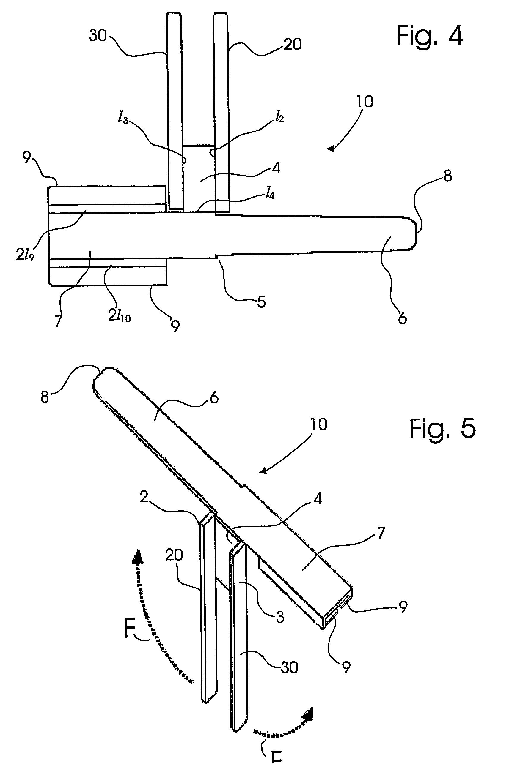
[0033]With reference to FIG. 4, therein the modular device according to the present invention, indicated as 10 as a whole, is shown by a plan view similar to that in FIG. 1.
[0034]For clarity sake, in describing the second embodiment similar reference numerals and signs are used to indicate parts that are identical or similar to those of the first embodiment. The second embodiment differs from the first embodiment as the edges 2, 3 extend from the body portion 4 to form legs 20, 30.
[0035]The punched plate blank in FIG. 4 is shown in its erected form, ready for its use, in the perspective view of FIG. 5. Therein the body portion 4 is shown bent orthogonally downwards, thus as if it penetrates the drawing sheet, and the two lateral legs 20 and 30 are bent substantially 90 degrees outwards. As for the first embodiment, the fins 9, 9 are bent to form a channel-shaped cross-section. The counter-rotating arrows F indicate that the lateral legs 20, 30 can be bent in the opposite direction t...
PUM
 Abstract
Description
Claims
Application Information
 - R&D
- Intellectual Property
- Life Sciences
- Materials
- Tech Scout
- Unparalleled Data Quality
- Higher Quality Content
- 60% Fewer Hallucinations
Browse by: Latest US Patents, China's latest patents, Technical Efficacy Thesaurus, Application Domain, Technology Topic, Popular Technical Reports.
© 2025 PatSnap. All rights reserved.Legal|Privacy policy|Modern Slavery Act Transparency Statement|Sitemap|About US| Contact US: help@patsnap.com


