Method and device for the fixation of a tendon graft

a technology of tendon graft and fixation method, which is applied in the field of fixation of tendon graft relative to bone, can solve the problems of complex implantation procedures of devices and techniques, and create a protuberance that can be problematic for patients

Active Publication Date: 2013-09-03
KARL STORZ GMBH & CO KG
View PDF13 Cites 9 Cited by
  • Summary
  • Abstract
  • Description
  • Claims
  • Application Information

AI Technical Summary

Benefits of technology

[0006]Accordingly, it is an object of the present invention to provide a method and device for easily and securely fixating a graft within a bone tunnel that is drilled at some non-perpendicular angle with respect to the outer surface of the bone, wherein the device lies flat against the surface of the bone.
[0013]These and other objectives may also be achieved by providing a fixation device for securing a transplant in a bone tunnel, comprising: a strap having a plurality of protrusions disposed along its length; a fastening member having an aperture therein for passing the strap; and a connection element disposed at a distal end of said strap for engaging a transplant. The aperture may traverse the fastening member at an angle such that a distal side of the fastening member may lie substantially flush against an outer surface of the bone. The fastening member may further comprise a self-locking element for engaging at least one of the protrusions and preventing said strap from moving in a distal direction when a tensile force is applied thereto.

Problems solved by technology

Damage to ligaments, such as anterior cruciate ligaments (ACL) and the posterior cruciate ligaments (PCL), cartilage, and tendons has become a relatively common occurrence and often requires surgical repair.
However, these known devices and techniques often require complicated implantation procedures or involve coordination of several discrete pieces.
Therefore, other known devices suffer from the problem that the anchoring device does not lie flush with the outer surface of the bone, creating a protuberance than can be problematic for the patient.

Method used


Image

  • Method and device for the fixation of a tendon graft
  • Method and device for the fixation of a tendon graft
  • Method and device for the fixation of a tendon graft

Examples


Embodiment Construction

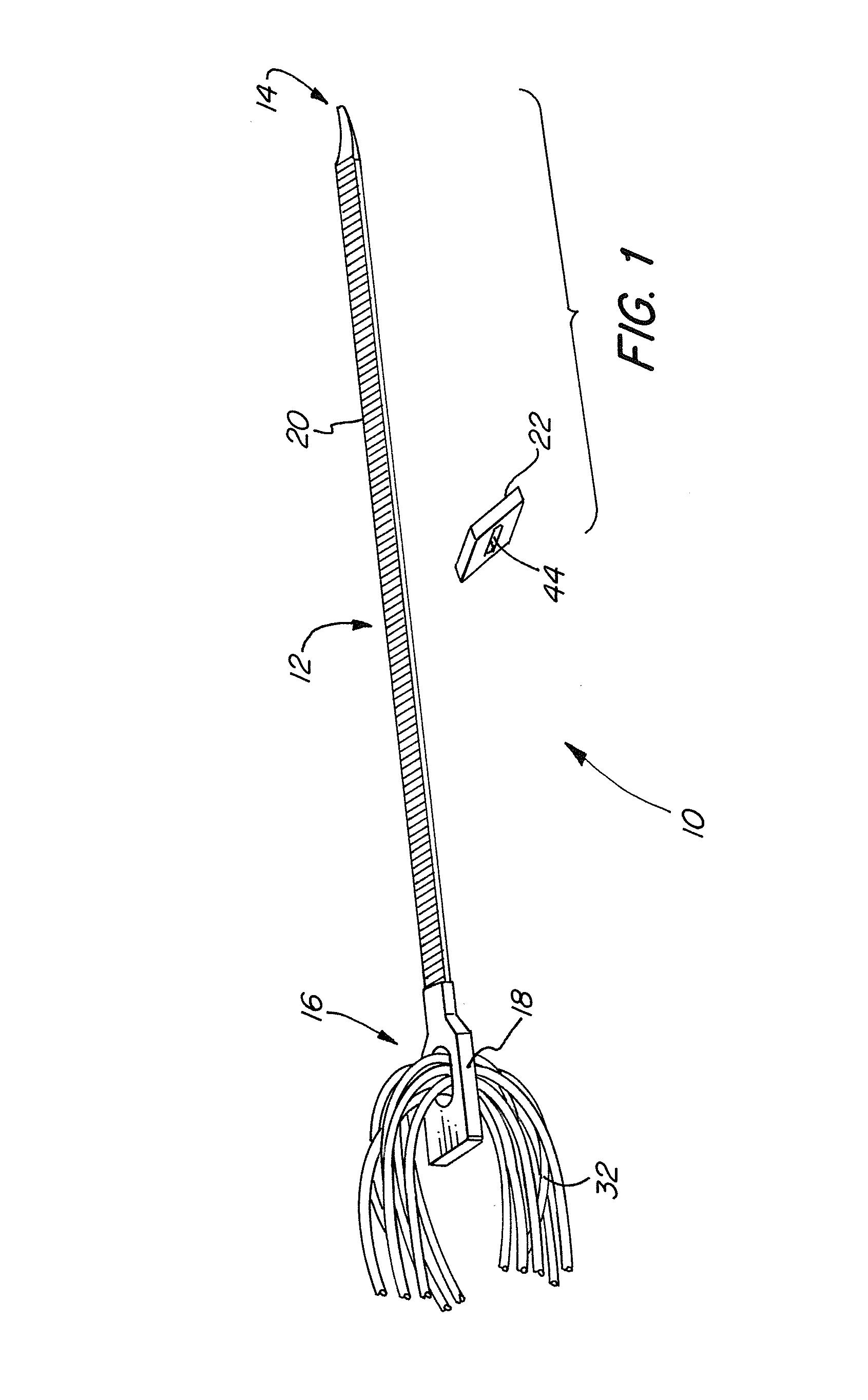
[0023]FIG. 1 depicts the fixation device 10 in accordance with the present invention, which comprises an elongate strap 12, having a proximal end 14 and a connection element 18 provided at a distal end 16 thereof, and a fastening member 22. Both the strap 12 and fastening member 22 may be made of a bioabsorbable material (such as that found in the MegaFix® interference screw), a plastic (such as PEEK) or any other suitable material.

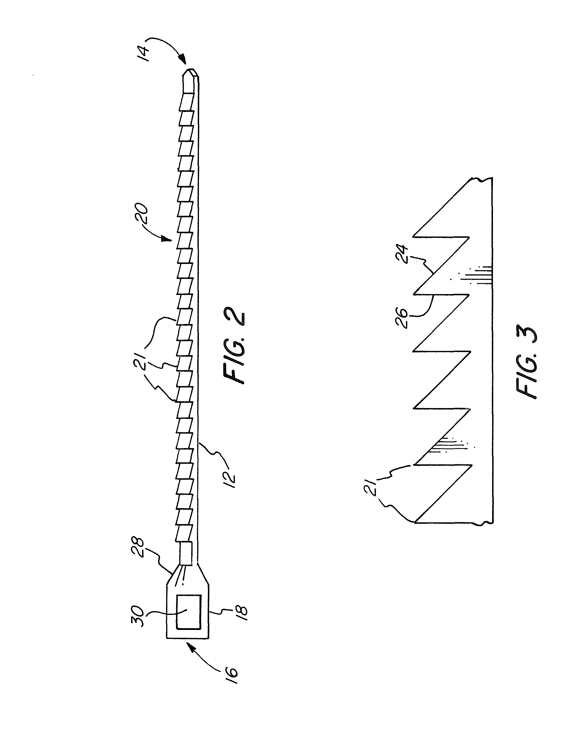
[0024]As shown in FIGS. 2 and 3, strap 12 further comprises a plurality of protrusions 20 along its length. In one embodiment, strap 12 is similar to a “zip-tie” or “cable-tie” known in the art, wherein the protrusions 20 are teeth 21, each having a proximal side 24 and a distal side 26, the distal side being formed at a right angle and the proximal side sloping downwards towards the proximal end 14 of the strap 12. Other configurations of the protrusions 20 are contemplated, including, but not limited to, a plurality of cones spaced along the strap. The ...


PUM


Abstract

A fixation device for securing a transplant in a bone tunnel, having a strap with a plurality of protrusions disposed along its length, a fastening member with an aperture therein for passing the strap, and a connection element disposed at a distal end of the strap for engaging a transplant is provided. The fixation device is configured such that, when the distal side of the fastening member lies substantially flush against an outer surface of the bone, a longitudinal axis of the aperture is substantially parallel to a longitudinal axis of the bone tunnel. A method for securing a transplant in a bone tunnel using the aforementioned fixation device is also provided.

Description

FIELD OF THE INVENTION[0001]The invention relates to a device and method for use in tissue repair or replacement, more specifically, to fixating a graft relative to a bone.BACKGROUND OF THE INVENTION[0002]Damage to ligaments, such as anterior cruciate ligaments (ACL) and the posterior cruciate ligaments (PCL), cartilage, and tendons has become a relatively common occurrence and often requires surgical repair. Often, the ACL or the PCL is ruptured or torn as a result of physical activity and, consequently, various surgical procedures have been developed for replacing or reconstructing these ligaments.[0003]The knee joint is often repaired by substituting a harvested or synthetic replacement ligament for the damaged one. Commonly, a substitute ligament or graft is inserted into tunnels reamed in the femur and tibia bones. Once anchored in place, the graft ligament is able to cooperate with the surrounding bone and tissues and thereby perform the functions of the damaged ACL or PCL.[00...

Claims


Application Information

Patent Timeline
Patent Type & Authority Patents(United States)
IPC IPC(8): A61F2/08A61B17/08
CPCA61F2/0811A61F2002/0829A61F2250/0007A61F2002/0882A61F2002/0852
Inventor HART, RICKEY
Owner KARL STORZ GMBH & CO KG
Why Eureka
Try Eureka