Filtering face-piece respirator having parallel line weld pattern in mask body

a mask body and filtering face technology, applied in the field of filtering facepiece respirator having parallel line weld pattern in the mask body, can solve the problems of reduced product cost and lower breathing resistance, and achieve the effect of preventing the mask body from collapsing during us

Active Publication Date: 2013-09-10
3M INNOVATIVE PROPERTIES CO
View PDF27 Cites 20 Cited by
  • Summary
  • Abstract
  • Description
  • Claims
  • Application Information

AI Technical Summary

Benefits of technology

[0007]The present invention provides a new filtering face-piece respirator construction that assists in preventing mask body collapse during use. The respirator of the present invention comprises a mask harness and a mask body where the mask body comprises a filtering structure that has a total thickness “A”. The filtering structure also has two or more parallel weld lines disposed therein that are spaced 0.5 to 6 times A.
[0008]The present invention is directed to providing a filtering face-piece respirator that possesses crush resistant properties that minimize mask body deformation caused by extended use or rough handling. The use of closely-spaced parallel weld lines may create a beam effect that makes the respirator less likely to lose its structural integrity from particle loading and moisture build-up. Filtering face-piece respirators that are less likely to collapse during use present the benefit of improving wearer comfort and convenience. Further, there is less need for additional layers or heavier layers to provide collapse resistant qualities. The use of less media in the mask body can result in lower breathing resistance and reduced product cost. The inventors also have discovered that faster welding speeds may be achieved when using two parallel weld lines that together have the same width as a single weld line. Because less surface area is welded using two parallel lines, less welding energy is required to bond the nonwoven fibrous materials; there is accordingly less risk of delamination, and so line speeds can be increased. Further, “welding flash” also tends to be minimized through use of closely-spaced parallel weld lines. “Welding flash” is excess material that was previously molten but becomes solidified along the edge or end of a weld line Welding flash can create an agglomerated bead of material and a hole in the mask body. When making a wide single weld, more material is melted, which has to be displaced in a rotary welding process. This “molten weld front” can get trapped in a converging embossing pattern and deposit “weld flash” on the trailing edge of the welded pattern. Because welding speeds can be increased and because less welding flash is experienced, manufacturing costs may be further reduced when producing a respirator that has closely-spaced parallel weld lines.GLOSSARY

Problems solved by technology

The use of less media in the mask body can result in lower breathing resistance and reduced product cost.

Method used


Image

  • Filtering face-piece respirator having parallel line weld pattern in mask body
  • Filtering face-piece respirator having parallel line weld pattern in mask body
  • Filtering face-piece respirator having parallel line weld pattern in mask body

Examples


examples

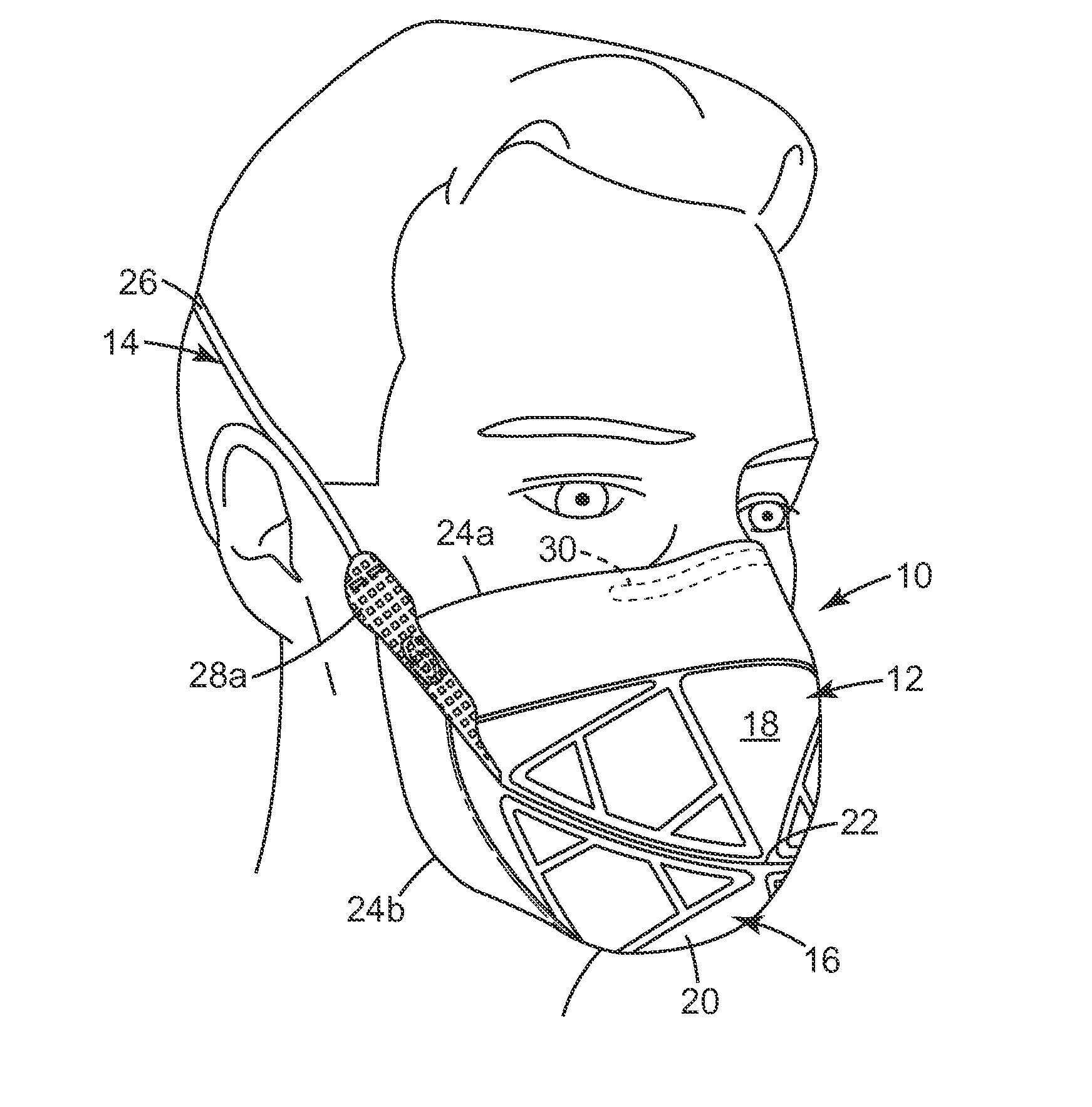
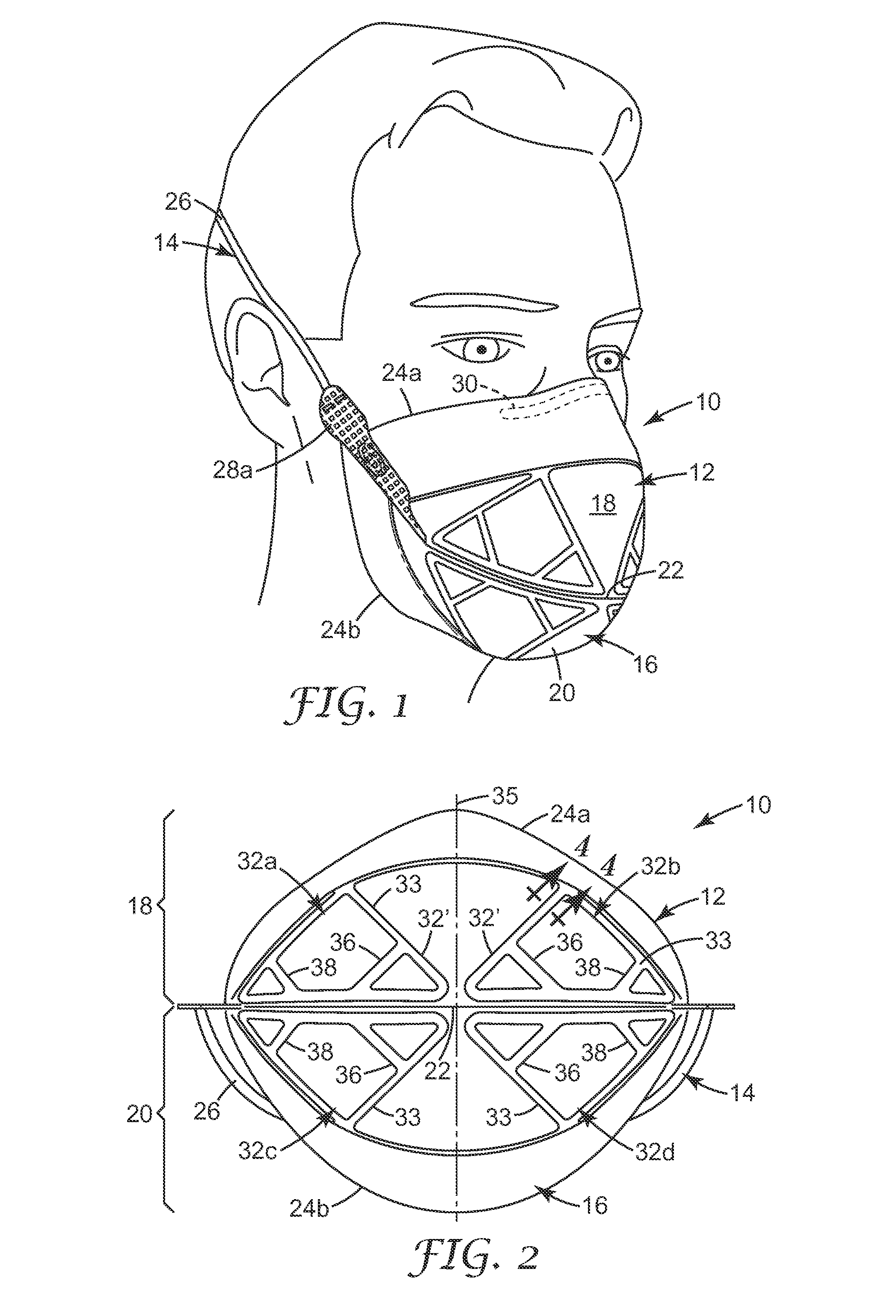
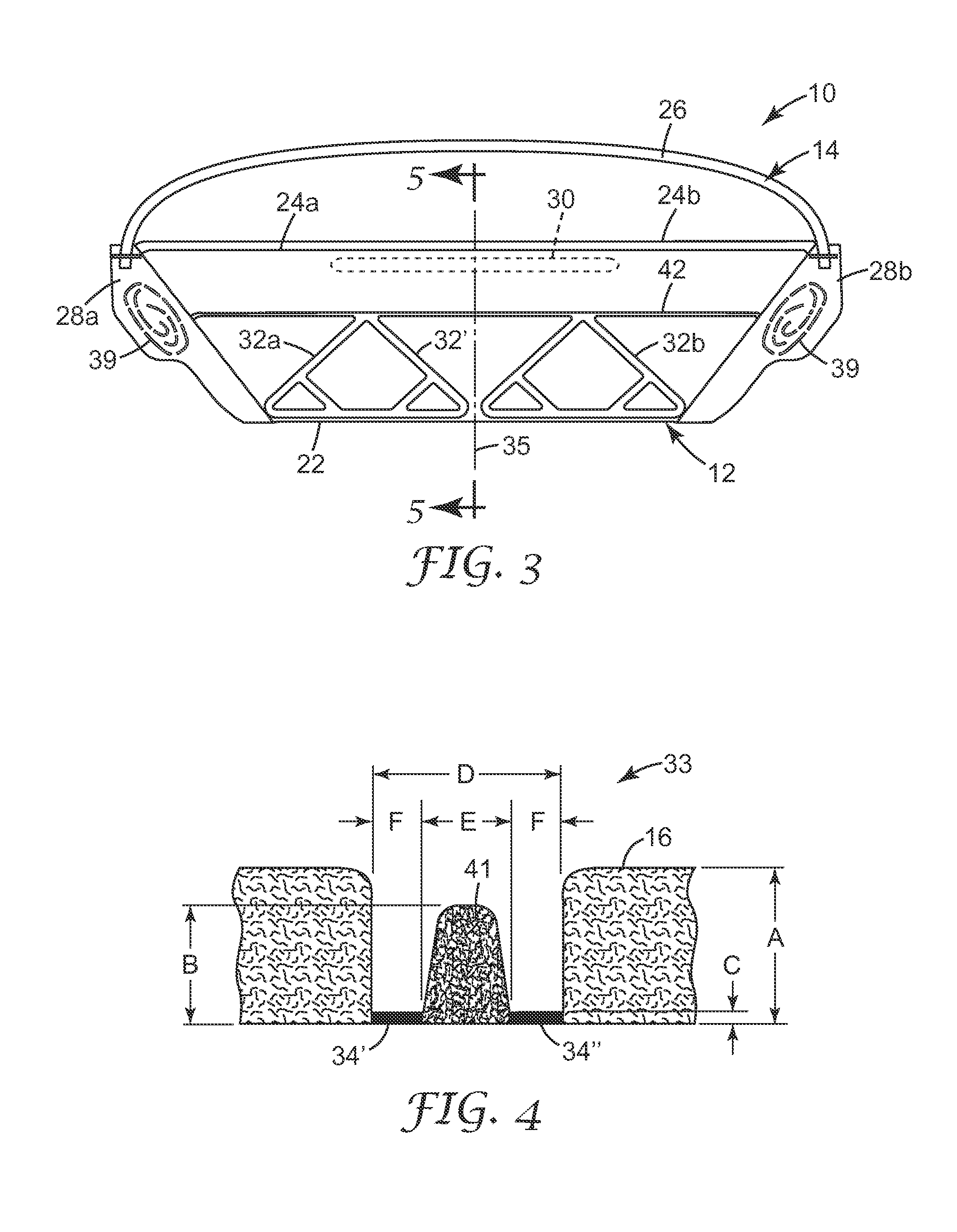
[0069]The invention improves the collapse resistance of flat-fold filtering facepiece respirators by increasing the stiffness of portions of the respirators, for example, 32a, 32b, 32c and 32d in FIG. 2. This is accomplished by using heat to compress and bond together the layers of the filtering structure 16 in FIG. 1. The Taber Stiffness Tester (Taber Industries, North Tonawanda, N.Y., USA) can be used to measure the stiffness of a variety of materials, including nonwoven materials which are often used in the construction of filtering facepiece respirators.

[0070]The Taber Stiffness Tester measures the stiffness of a strip of material by determining the amount of torque required to deflect the sample by a specified amount, typically 15°. The result of a test conducted with the Taber Stiffness Tester is reported in Taber Stiffness Units. One Taber Stiffness Unit is defined as the stiffness required for 1 cm long sample to be deflected 15° when a torque of 1 gm-cm is applied to one en...


PUM


Abstract

A respirator 10 that has a harness 14 and a mask body 12 that is joined to the harness 14. The mask body 12 includes a filtering structure 16 that may contain a plurality of layers of nonwoven fibrous material 58, 60, 62. The layers of nonwoven fibrous material 58, 60, 62 have a thickness A and are welded together by at least two parallel weld lines 34′, 34″ that are spaced at 0.5 to 6 times A. A mask body that uses parallel weld lines may exhibit better resistance to collapse and may be manufactured at faster speeds than similar structures which use single weld lines of comparable width.

Description

CROSS-REFERENCE TO RELATED APPLICATION[0001]This application claims the benefit of U.S. Provisional Patent Application No. 61 / 254,314, filed Oct. 23, 2009.[0002]The present invention pertains to a filtering face-piece respirator that has a weld pattern disposed on its mask body, which weld pattern includes two or more closely-spaced parallel weld lines.BACKGROUND[0003]Respirators are commonly worn over the breathing passages of a person for at least one of two common purposes: (1) to prevent impurities or contaminants from entering the wearer's breathing track; and (2) to protect other persons or things from being exposed to pathogens and other contaminants exhaled by the wearer. In the first situation, the respirator is worn in an environment where the air contains particles that are harmful to the wearer, for example, in an auto body shop. In the second situation, the respirator is worn in an environment where there is risk of contamination to other persons or things, for example,...

Claims


Application Information

Patent Timeline
Patent Type & Authority Patents(United States)
IPC IPC(8): A62B7/10
CPCA62B23/025A41D13/1138A41D13/1161
Inventor DUFFY, DEAN R.
Owner 3M INNOVATIVE PROPERTIES CO
Why Eureka
Try Eureka