
Device for stripping off material from a conveyor belt of a belt conveyor

Active Publication Date: 2013-09-10
SCRAPETEC
View PDF13 Cites 5 Cited by
  • Summary
  • Abstract
  • Description
  • Claims
  • Application Information

AI Technical Summary

Benefits of technology

The present invention provides a device for cleaning conveyor belts that is adapted to the belt surface better, requires less space and provides a gentle treatment of the conveyor belt. The device includes a stripping body with a carrying element and a liftoff element that facilitate an optimum adaptation of the stripping body to the belt surface and an improved cleaning effect. The device is easy to install and replace worn body segments quickly with new ones. The stripping elements have improved wear resistance and are configured to partially overlap, which further improves the cleaning performance. A spring element is provided to achieve good compression of the stripping element at the conveyor belt and a deflection of the stripping element when contacting a foreign object.

Problems solved by technology

The stripping devices known from DE 801 144 and U.S. Pat. No. 2,878,926 have not really succeeded in the market, probably because their cleaning effect in particular for a relatively sticky feed material is not satisfactory.

Method used


Image

  • Device for stripping off material from a conveyor belt of a belt conveyor
  • Device for stripping off material from a conveyor belt of a belt conveyor
  • Device for stripping off material from a conveyor belt of a belt conveyor

Examples


Embodiment Construction

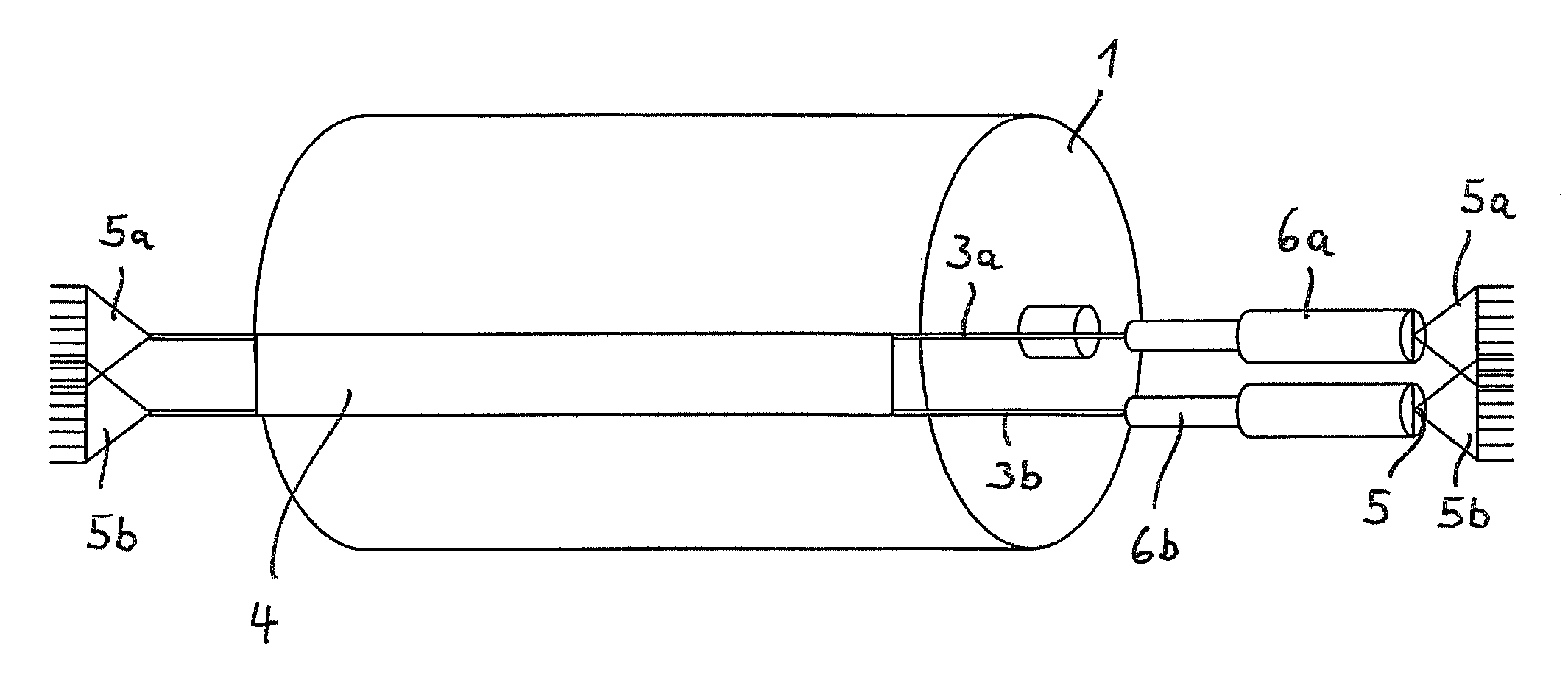
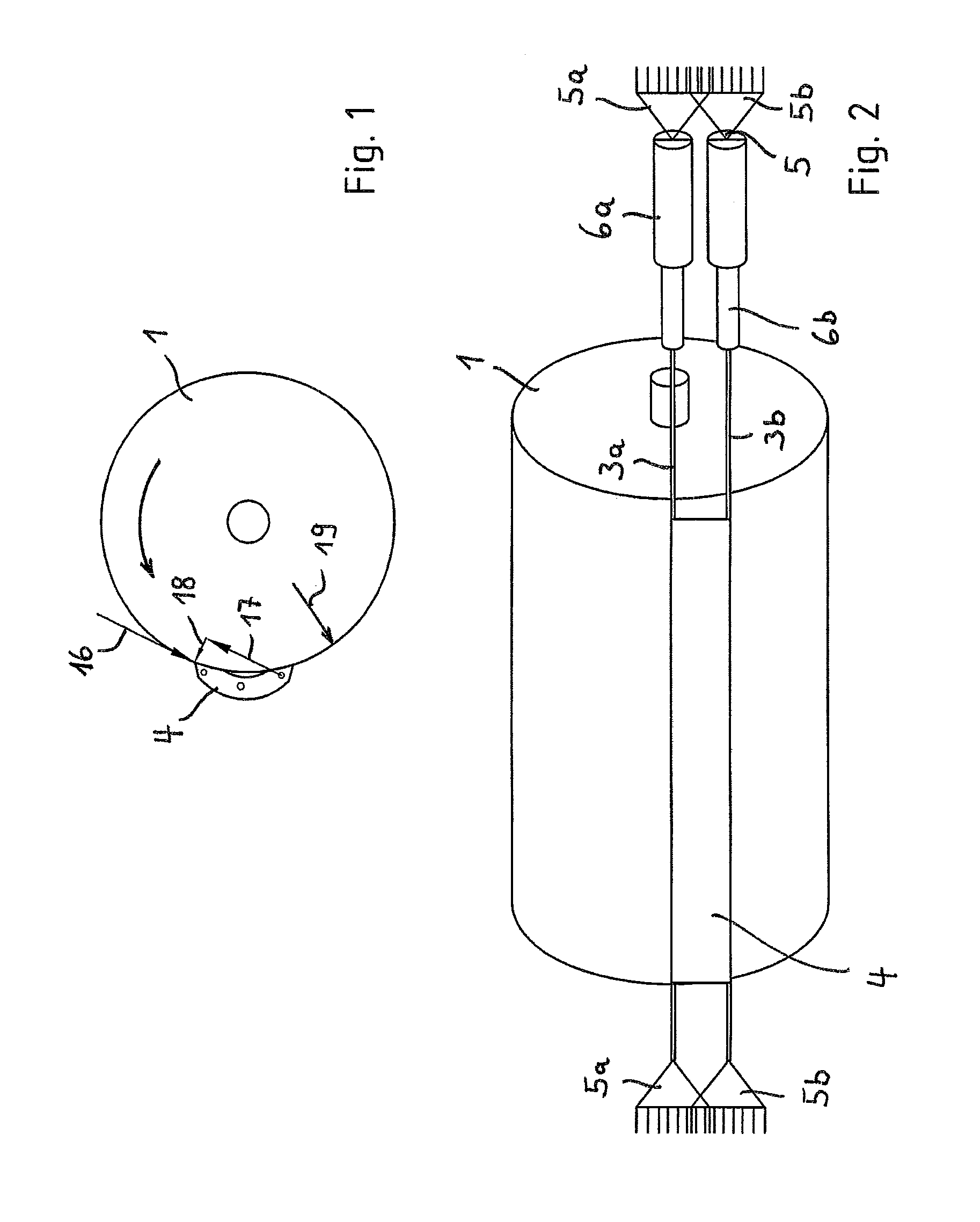
[0046]The FIGS. 1 and 2 illustrate a discharge or pulley drum 1 of a belt conveyor. The running direction of the conveyor belt or the rotating direction of the drum 1 is represented by an arrow.

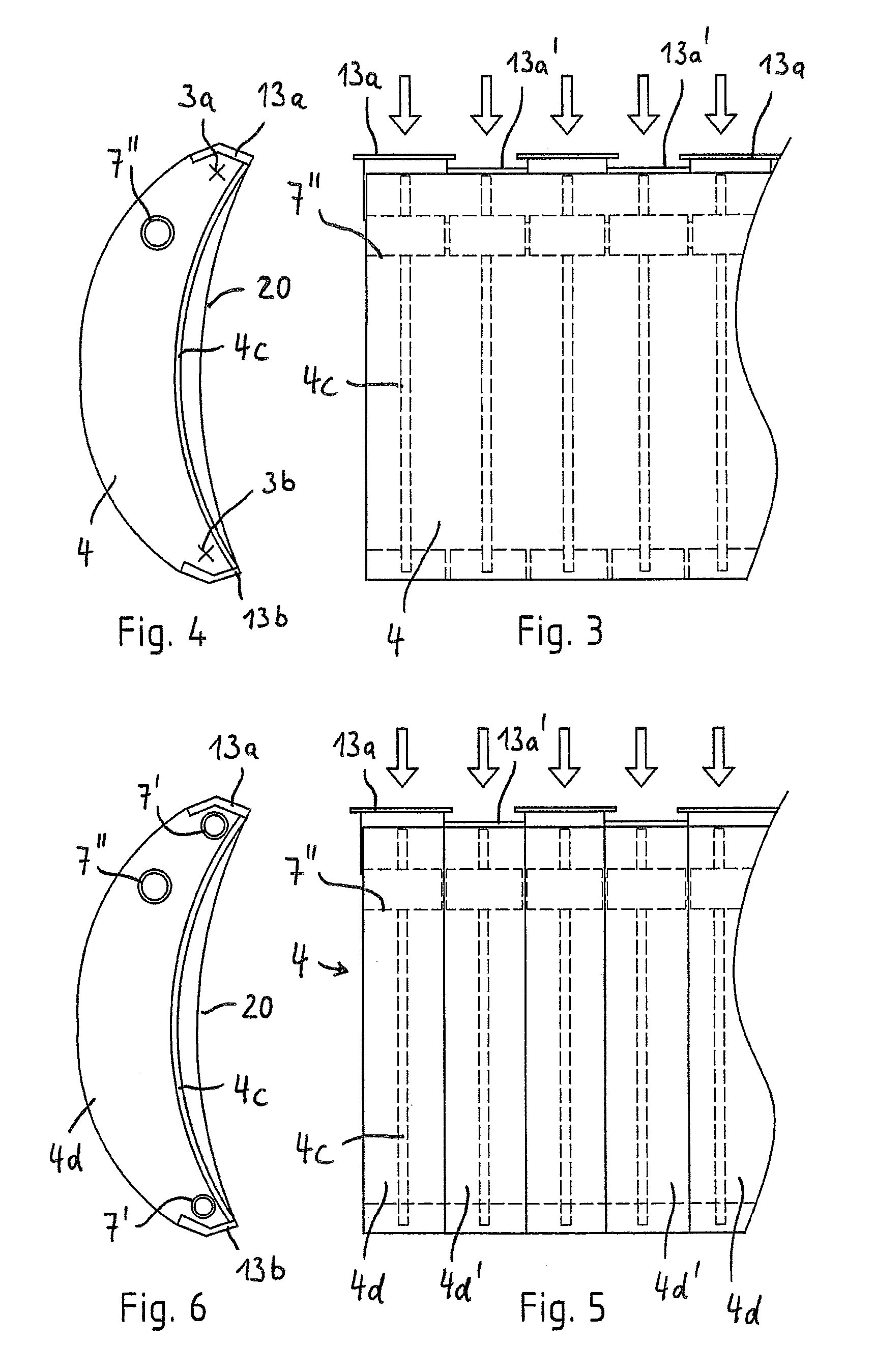
[0047]At the curve of the discharge drum 1, enveloped by the belt, thus below the area where the feed material (not shown) is discharged from the conveyor belt, a stripping body of one-part or multi-part configuration is disposed. Material to be conveyed still adhering to the belt is separated from the belt through the stripping body 4.

[0048]The length of the stripping body 4 corresponds approximately to the axial length of the drum 1, at least however, to the width of the conveyor belt. The stripping body 4 is made from material that bends elastically, preferably plastic material and / or elastomeric material. The stripping body 4 is provided with a carrying element 3a, e.g. a metal chain, in particular a steel chain, through which it is pulled against the conveyor belt. The stripping body 4 i...


PUM


Abstract

A device for stripping material from a conveyor belt of a belt conveyor in the area of a curve of a discharge drum below a discharge location of the belt conveyor, comprising a stripping body provided with a carrying element through which the stripping body is pulled or pullable against the conveyor belt, wherein the stripping body is further provided with a lift-off element which is disposed in the stripping body and offset from the carrying element and supports the stripping body when the latter is displaced in the belt running direction. The stripping body may include a plurality of stripping elements which define stripping edges and which have improved wear resistance compared to a material of the stripping body, wherein the stripping elements are configured and / or arranged, so that the stripping edges of adjacent stripping elements overlap partially overlap.

Description

BACKGROUND OF THE INVENTION[0001]1. Field of the Invention[0002]The invention relates to a device for stripping off material from a conveyor belt of a belt conveyor in a region of a curve of a discharge drum below a discharge location of the belt conveyor, having a stripping body which is of one-part or multi-part configuration.[0003]2. Description of Related Art[0004]Conventional stripping devices for belt conveyors, which devices are disposed in the region of the discharge drum, extend parallel to the drum axis. Furthermore, stripping devices for rotating drums or belt conveyors are known, in which a wire is used as a stripping body, wherein the wire is tensioned transversally across the surface of the drum or pulled in a helical manner over a portion of the circumference of the drum. Thus, the wire is provided with a tension spring at one end or at both ends, wherein the tension spring puts the wire under tension (DE 801 144).[0005]A similar stripping device is known from the U.S...

Claims


Application Information

Patent Timeline
IPC IPC(8): B65G45/00
CPCB65G45/12B65G45/16
Inventor DUNNWALD, WILFRIED
Owner SCRAPETEC
Learn More