Method of forming a fully wrapped-around shielded PMR writer pole

a technology of shielding and writer poles, applied in the field of magnetic recording, can solve the problems of adjacent track interference (ati), formidable obstacle to providing a clean interface between ls and ss, and difficult to reach a standard parallel plate etching technique such as sputter etching, and achieve the effect of reducing or eliminating the shadowing effect and improving the deposition coverag

Inactive Publication Date: 2013-09-17
WESTERN DIGITAL TECH INC
View PDF12 Cites 161 Cited by
  • Summary
  • Abstract
  • Description
  • Claims
  • Application Information

AI Technical Summary

Benefits of technology

[0006]The present disclosure addresses this and other problems by utilizing an ion beam etching (IBE) process with tunable tilt angles to reduce or eliminate the shadowing effect associated with the conventional sputter etching process, and, in some embodiments, by further utilizing a suitable ion beam deposition (IBD) process performed at an optimized angle to obtain better deposition coverage around pole.

Problems solved by technology

But the re-entrant shape of pole and surrounding structures produces a shadowing effect which makes it extremely difficult for a standard parallel plate etching technique such as the sputter etching to reach and clean the target SS deposition area around the pole, especially in the bottom corner of the pole.
As illustrated in FIGS. 1B and C, the black line to be removed is trapped in the deep bottom of a well which is surrounded by the overhang above the main pole, inclined side gap, and leading bevel slope, which present a formidable obstacle to providing a clean interface between the LS and the SS.
The presence of the dark line compromises the structural integrity and / or produces a magnetic discontinuity between the LS and SS regions, which in turn can cause adjacent track interference (ATI) issues in the resulting FWAS PMR writer pole.

Method used


Image

  • Method of forming a fully wrapped-around shielded PMR writer pole
  • Method of forming a fully wrapped-around shielded PMR writer pole
  • Method of forming a fully wrapped-around shielded PMR writer pole

Examples


Embodiment Construction

[0015]In the following detailed description, numerous specific details are set forth to provide a full understanding of the present invention. It will be apparent, however, to one ordinarily skilled in the art that the present invention may be practiced without some of these specific details. In other instances, well-known structures and techniques have not been shown in detail to avoid unnecessarily obscuring the present invention.

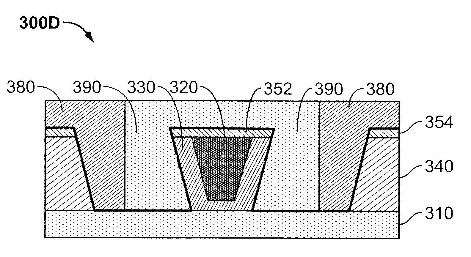
[0016]FIG. 2 is a flowchart illustrating an exemplary process 200 for forming a fully wrapped-around shielded (FWAS) perpendicular magnetic recording (PMR) writer pole according to certain aspects of the present disclosure. FIGS. 3A-D represent a sequence of diagrams illustrating various exemplary intermediate structures arrived at during the course of the exemplary process 200 of FIG. 2 according to certain aspects of the present disclosure. For ease of illustration, without any intent to limit the scope of disclosure in any way, the exemplary fabricatio...


PUM

PropertyMeasurementUnit
tilt angleaaaaaaaaaa
magneticaaaaaaaaaa

Abstract

A method or forming a wrapped-around shielded perpendicular magnetic recording writer pole is disclosed. A structure comprising a leading shield layer and an intermediate layer disposed over the leading shield layer is provided, the intermediate layer comprising a pole material and a dielectric material. A trench is formed in the dielectric material. A non-magnetic layer in the trench is removed via an ion beam etching process. A seed layer is deposited in the trench and over the pole material. A magnetic material comprising a side shield layer is deposited on at least a portion of the seed layer.

Description

FIELD OF THE INVENTION[0001]The present invention generally relates to magnetic recording and, in particular, relates to method of forming a fully wrapped-around shielded PMR writer pole.BACKGROUND[0002]The increasing need for high recording area densities (up to 500 Gb / in2) is making the perpendicular magnetic recording head (PMR head) a replacement of choice for the longitudinal magnetic recording head (LMR head).[0003]In fully wrapped-around shielded (FWAS) PMR writer heads, a continuous shield surrounding the pole provides a continuous magnetic flux from leading shield (LS) to side shield (SS). In order to achieve a seamless interface between the leading shield and side shield block, an appropriate pre-etch step is adopted to provide a clean surface on leading shield before side shield seed deposition. But the re-entrant shape of pole and surrounding structures produces a shadowing effect which makes it extremely difficult for a standard parallel plate etching technique such as ...

Claims


Application Information

Patent Timeline
Patent Type & Authority Patents(United States)
IPC IPC(8): G11B5/127H04R31/00
CPCH04R31/00G11B5/3116G11B5/1278G11B5/3163G11B5/315Y10T29/49039Y10T29/49044Y10T29/49043Y10T29/49052Y10T29/49046Y10T29/49048G11B5/112G11B5/1276G11B5/3153
Inventor WANG, JINWENSI, WEIMINFANG, JIANXINHONG, YINGJIANG, HONGZHOULU, CHING-HUANGCHEN, YANLI, DONGHONGWANG, LIEN-CHANGZHONG, LIEPINGPAN, TAO
Owner WESTERN DIGITAL TECH INC
Why Eureka
Try Eureka