Tiltable sunshade

a sunshade and tilting technology, applied in the field of sunshade, can solve the problems of user standing below the canopy, falling off, and bending of the exposed portion of the cable, and achieve the effect of facilitating the description of the invention

Active Publication Date: 2013-09-17
TUNG BENSON
View PDF12 Cites 28 Cited by
  • Summary
  • Abstract
  • Description
  • Claims
  • Application Information

AI Technical Summary

Benefits of technology

[0037]All figures are drawn for ease of explanation of the basic teachings of the present invention only; the extensions of the figures with respect to number, position, relationship, and dimensions of the parts to form the preferred embodiments will be explained or will be within the skill of the art after the following teachings of the present invention have been read and understood. Further, the exact dimensions and dimensional proportions to conform to specific force, weight, strength, and similar requirements will likewise be within the skill of the art after the following teachings of the present invention have been read and understood.
[0038]Where used in the various figures of the drawings, the same numerals designate the same or similar parts. Furthermore, when the terms “first”, “second”, “lower”, “upper”, “outer”, “inner”, “end”, “portion”, “section”, “longitudinal”, “radial”, “annular”, “spacing”, and similar terms are used herein, it should be understood that these terms have reference only to the structure shown in the drawings as it would appear to a person viewing the drawings and are utilized only to facilitate describing the invention.

Problems solved by technology

However, the exposed portion of the cable is liable to break by an external force or an excessive pulling force.
Furthermore, when the sunshade is under a strong wind load, the force acting on the canopy is imparted to the handle, leading to loosening of the cable and bounce of the tilted canopy.
As a result, the user standing below the canopy may be injured.

Method used


Image

  • Tiltable sunshade
  • Tiltable sunshade
  • Tiltable sunshade

Examples


Embodiment Construction

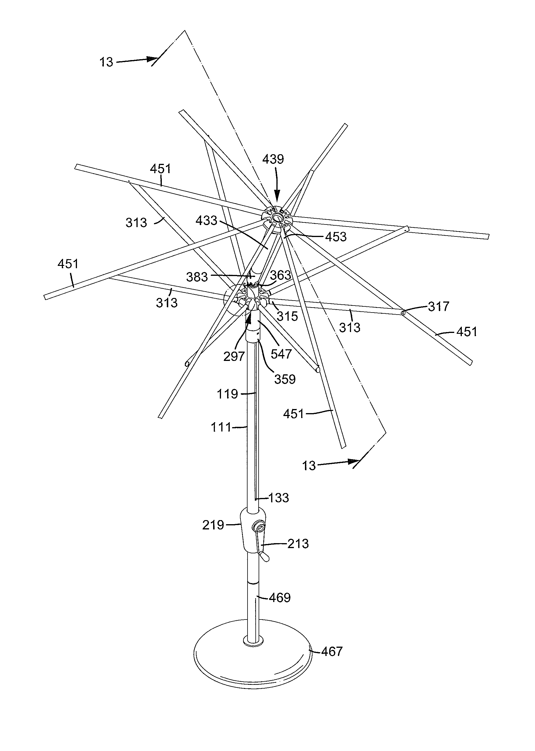
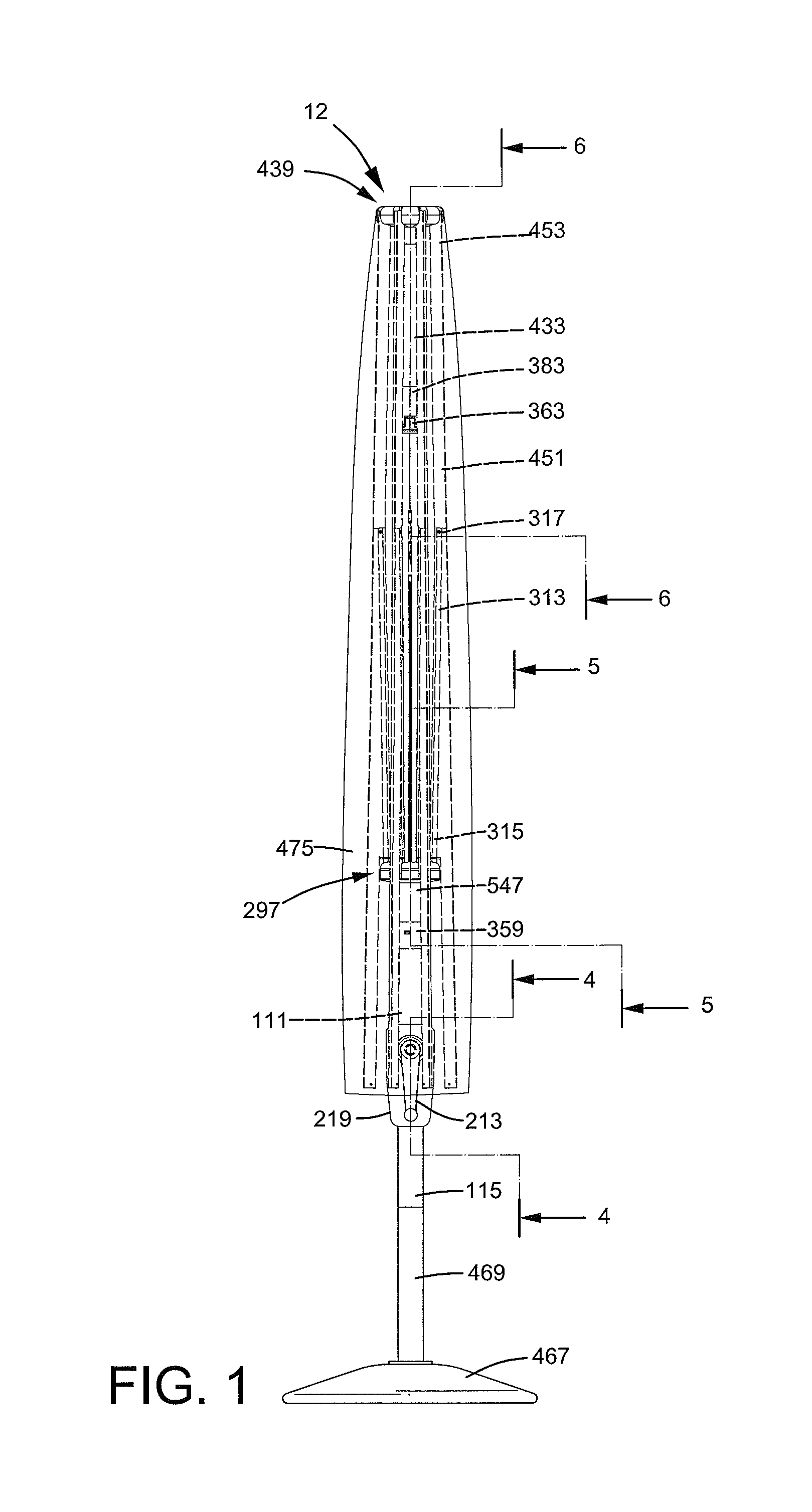
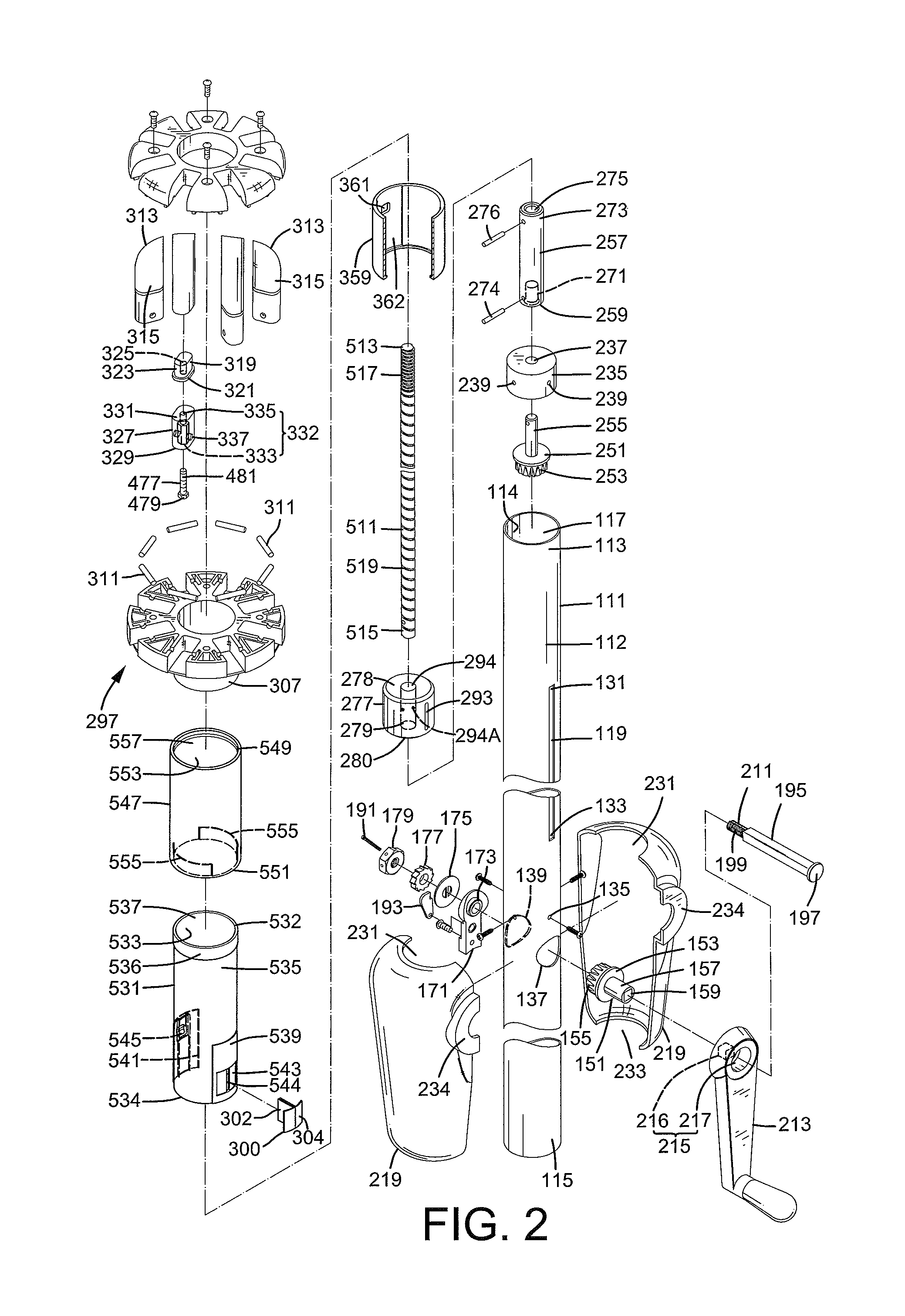
[0039]A tiltable sunshade according to the present invention is shown in the drawings and generally designated 12. Tiltable sunshade 12 includes a pole 111 having upper and lower ends 113 and 115 spaced along a longitudinal axis of pole 111. Pole 111 further includes inner and outer peripheries 114 and 112 extending between upper and lower ends 113 and 115, with inner and outer peripheries 114 and 112 spaced from each other in a radial direction perpendicular to the longitudinal axis of pole 111, and with inner periphery 114 defining a longitudinal hole 117. A slot 119 extends from outer periphery 112 through inner periphery 114 in the radial direction and includes first and second ends 131 and 133, with first end 131 of slot 119 located between upper end 113 of pole 111 and second end 133 of slot 119 along the longitudinal axis of pole 111. First and second holes 137 and 139 extend from outer periphery 112 through inner periphery 114 and are aligned with each other, with each of fi...


PUM


Abstract

A tiltable sunshade (12) includes a pole (111) rotatably receiving a screw rod (511) that can be rotated by operating a handle (213) to cause movement of a follower (277) in the pole (111) between a folded position, an unfolded position, and a tilted position to fold ribs (451), unfold the ribs (451), and tilt the ribs (451), respectively. The screw rod (511) has a large pitch portion (519) and a small pitch portion (517). When the follower (277) moves between the folded position and the unfolded position, the follower (277) moves along the large pitch portion (519) at a first speed. When the follower (277) moves between the unfolded position and the tilted position, the follower (277) moves along the small pitch portion (517) at a second speed smaller than the first speed.

Description

BACKGROUND OF THE INVENTION[0001]The present invention relates to a sunshade and, more particularly, to a sunshade that can be tilted according to the position of the sun.[0002]A type of outdoor sunshade includes a pole located on the ground and a plurality of ribs each having an end pivotably connected to a top end of the pole. A runner is slideably mounted to the pole. A plurality of stretchers is pivotably connected between the runner and the ribs. A canopy is provided on the ribs. A handle is fixed on a shaft rotatably mounted to the pole. An end of a cable is fixed to a portion of the shaft inside the pole, with the other end of the cable extending out of the pole and fixed to the runner. Rotation of the handle causes the canopy to move from a folded state to an unfolded state. Further rotation of the handle causes the canopy to tilt. Thus, a user can adjust the tilting angle of the canopy according to the position of the sun. However, the exposed portion of the cable is liable...

Claims


Application Information

Patent Timeline
Patent Type & Authority Patents(United States)
IPC IPC(8): A45B17/00
CPCA45B17/00A45B2017/005A45B2023/0012
Inventor TUNG, BENSON
Owner TUNG BENSON
Why Eureka
Try Eureka