
Reversible electromagnetic contactor

a contactor and electromagnetic technology, applied in the direction of circuit-breaking switches, relays, circuit-breaking switches for excess current, etc., can solve the problems of increased device cost, reduced size, increased outer dimensions, etc., and achieve the effect of reducing size and cost, simplifying electrical interlocking, and unnecessary auxiliary contact unit expenses

Active Publication Date: 2013-09-17
FUJI ELECTRIC FA COMPONENTS & SYST CO LTD
View PDF13 Cites 2 Cited by
  • Summary
  • Abstract
  • Description
  • Claims
  • Application Information

AI Technical Summary

Benefits of technology

The present invention aims to provide a reversible electromagnetic contactor that allows for mechanical and electrical interlock to prevent two electromagnetic contactors from being closed simultaneously, without requiring additional auxiliary contacts. The contactor also enables size and cost reduction. The technical effects of the invention include simplifying the electrical interlock process and reducing the need for additional auxiliary contacts, leading to a smaller and less expensive contactor.

Problems solved by technology

Meanwhile, in the case of the two electromagnetic contactors which incorporate only one pole of the auxiliary contacts of the normally-closed contacts (contacts (b)), since the auxiliary contacts of the incorporated normally-closed contacts (contacts (b)) are used for the electrical interlock, when another additional circuit such as an auto-holding circuit and a signal circuit is wished to be connected, an auxiliary contact unit is required, and the problems are associated with the reduction in size due to the increase in the outer dimensions and with the increase in the device cost caused by the use of the auxiliary contact unit.

Method used


Image

  • Reversible electromagnetic contactor
  • Reversible electromagnetic contactor
  • Reversible electromagnetic contactor

Examples


Embodiment Construction

[0045]The best mode (referred to hereinbelow as “embodiment”) for carrying out the reversible electromagnetic contactor in accordance with the present invention will be explained in detail hereinbelow with reference to the appended drawings. Structural components identical to those shown in FIGS. 1 and 12 are assigned with same reference numerals and the explanation thereof is herein omitted.

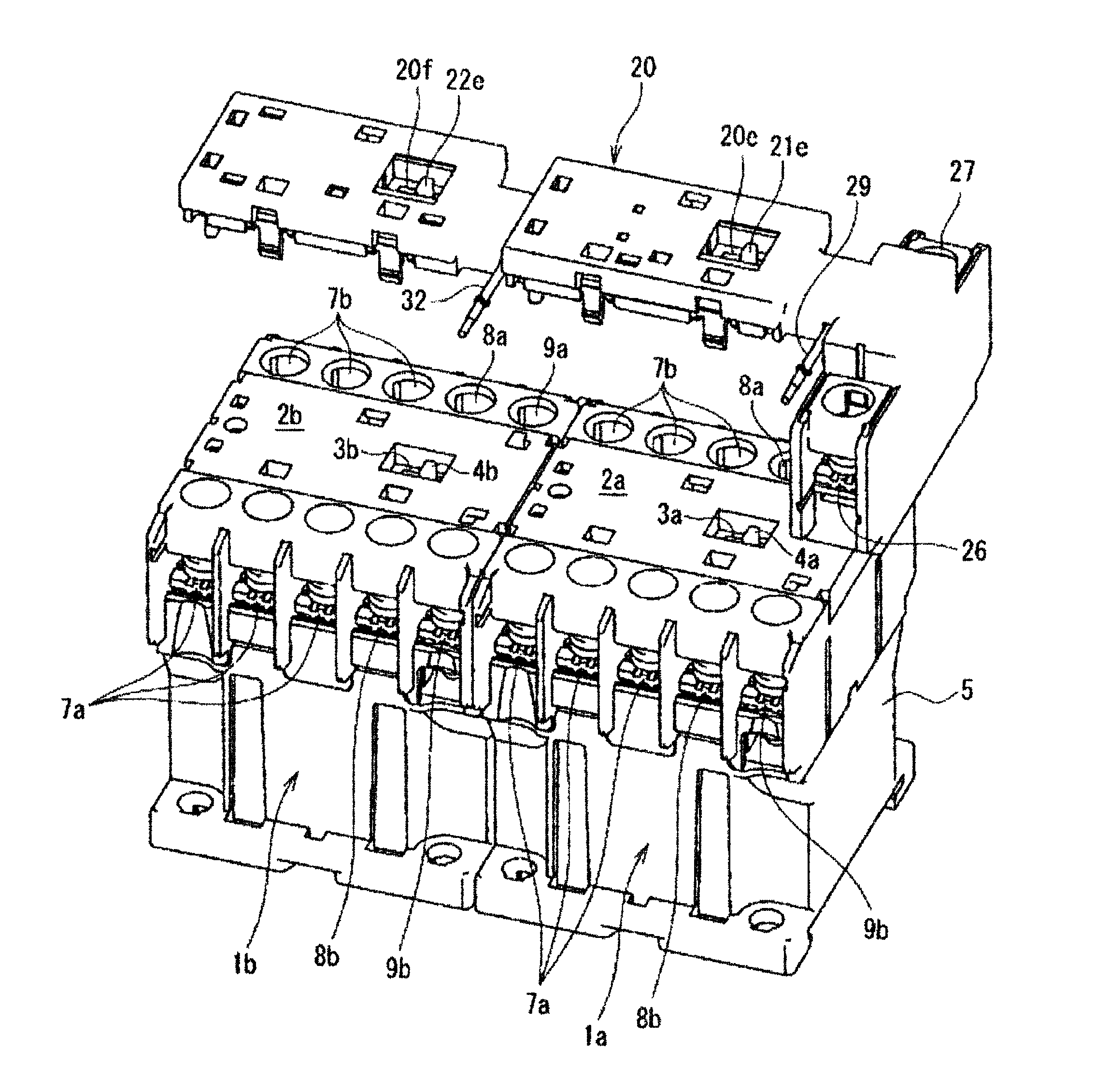
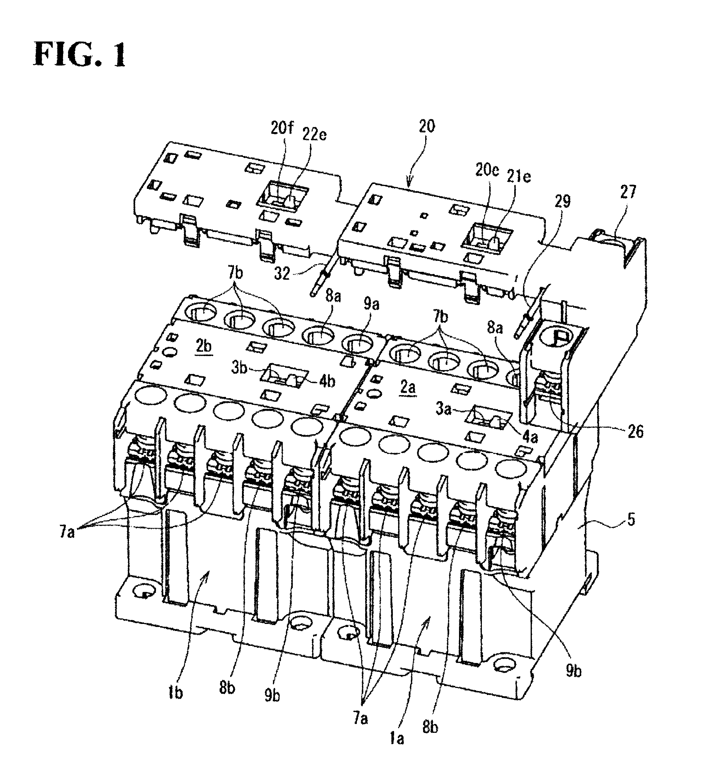
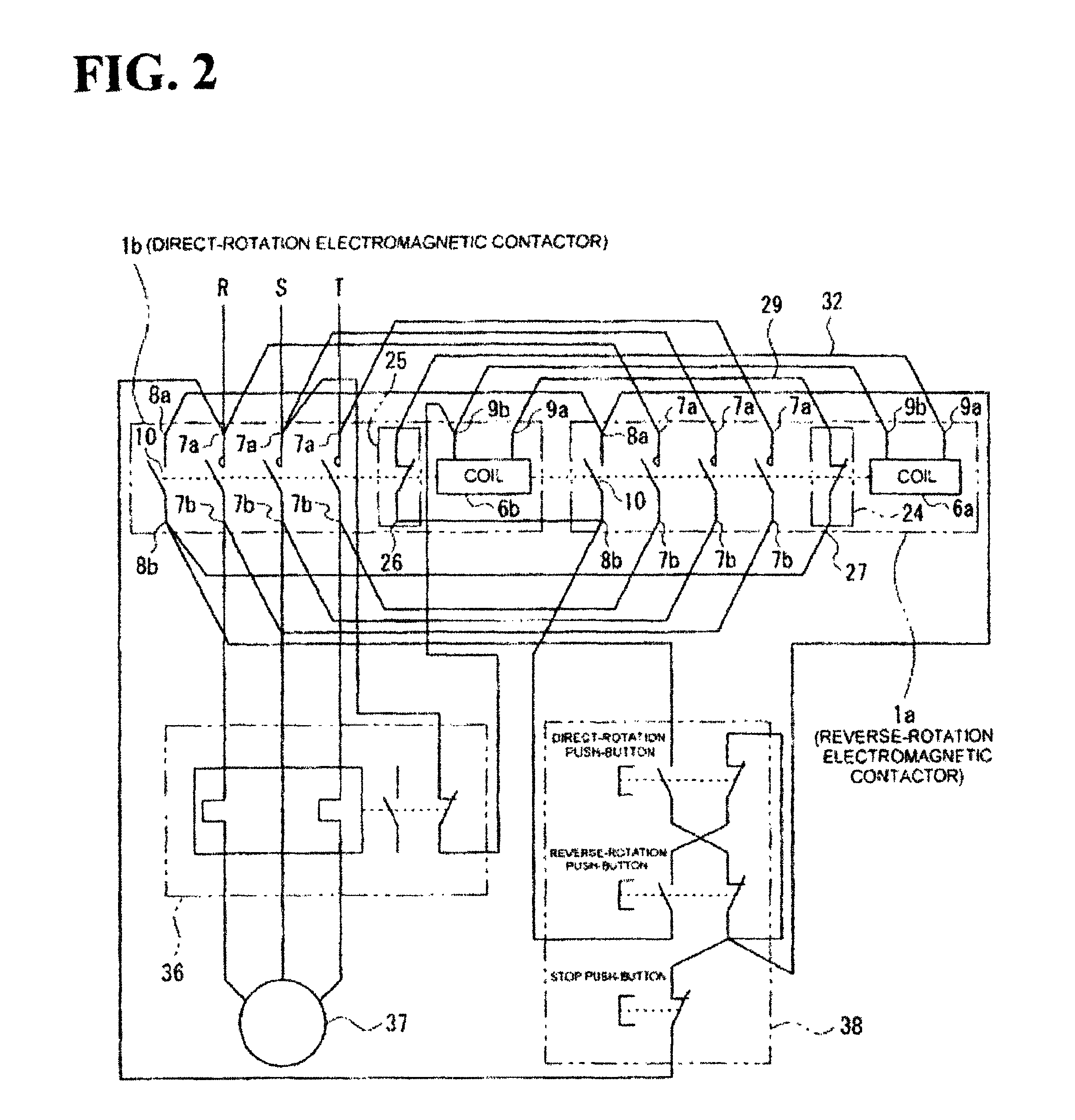
[0046]FIG. 1 illustrates an embodiment of the reversible electromagnetic contactor. FIG. 2 shows an embodiment of the control circuit of an induction motor provided with the reversible electromagnetic contactor shown in FIG. 1.

[0047]As shown in FIG. 1, the reversible electromagnetic contactor according to the present embodiment has two electromagnetic contactors 1a, 1b disposed adjacently, and a reversible unit 20 is mounted across these electromagnetic contactors 1a, 1b.

[0048]In the electromagnetic contactor 1a shown in FIG. 1, a fixed iron core (not shown in the figure), a movable iron core (...


PUM


Abstract

A reversible unit (20) has a pair of interlock plates (21, 22) detachably connected to operation indication pieces (4a, 4b) of a pair of electromagnetic contactors (1a, 1b) and moving in the same direction as the moving direction of the operation indication pieces, a lock piece (23) connecting with the pair of interlock plates (21, 22), a first normally-closed contact (24), and a second normally-closed contact (25). In a closing operation of one of the electromagnetic contactors (1a), the lock piece (23) moves one of the interlock plates (21) and prohibits the movement of the other interlock plate (22). The first normally-closed contact (24) is connected in series in a power supply circuit to an exciting coil (6b) of the other electromagnetic contactor (1b). One of the interlock plates (21) has a first opening operation engagement portion (34) releasing the first normally-closed contact (24) when the interlock plate (21) moves.

Description

RELATED APPLICATIONS[0001]The present application is National Phase of International Application No. PCT / JP2010 / 005586 filed Sept. 13, 2010, and claims priority from Japanese Application No. 2010-018288, filed Jan. 29, 2010.TECHNICAL FIELD[0002]The present invention relates to a reversible electromagnetic contactor that mechanically and electrically interlocks simultaneous closing of two electromagnetic contactors of two electromagnetic contactors disposed adjacently, by using a reversible unit.BACKGROUND ART[0003]For example, a device in which a reversible unit is mounted across two adjacently disposed electromagnetic contactors and the reversible unit is mechanically interlocked so as to prevent the two electromagnetic contactors from being closed simultaneously (simultaneous ON operation) is known as a reversible electromagnetic contactor that is connected to the control circuit of an induction motor and performs direct-reverse operation control of the induction motor (for exampl...

Claims


Application Information

Patent Timeline
Patent Type & Authority Patents(United States)
IPC IPC(8): H01H73/12
CPCH01H50/323H01H9/26H01H2050/325H01H50/04
Inventor TAKAYA, KOUETSUOKUBO, KOJINAKA, YASUHIROSUZUKI, KENJI
Owner FUJI ELECTRIC FA COMPONENTS & SYST CO LTD
Features
  • Generate Ideas
  • Intellectual Property
  • Life Sciences
  • Materials
  • Tech Scout
  • Unparalleled Data Quality
  • Higher Quality Content
  • 60% Fewer Hallucinations
Learn More