
Rain catch for collecting and diverting rainwater from a retractable awning

a retractable awning and rainwater technology, applied in the field of rainwater capture and diversion, can solve the problems of mud splatter, affecting the easy retraction and storage of rainwater, and the practicality of the gutter system, so as to facilitate the diversion of rainwater, facilitate the installation, and facilitate the effect of collecting water

Inactive Publication Date: 2013-09-24
ZIEGLER TOM
View PDF20 Cites 0 Cited by
  • Summary
  • Abstract
  • Description
  • Claims
  • Application Information

AI Technical Summary

Benefits of technology

The patent describes a rain catch that is easy to install and remove on a retractable awning. The catch collects rainwater from the top of the awning, which can then be redirected to a more convenient location. The catch is attached to the awning beam and has a cavity with an opening that allows for the collection of rainwater. The rainwater is then funneled through a downspout port. The end of the downspout is typically directed away from the immediate perimeter area of the awning to avoid excessive water shedding. The rain catch and diverter is ideal for temporary awnings that are regularly retracted and re-deployed on a regular basis.

Problems solved by technology

This can cause problems such as erosion, mud splatter, and even flooding of the very area the awning is intended to shield from the rain.
Such a gutter system, however, is really only practical when applied to awnings that are intended to be permanently (or at least semi-permanently) deployed.
Any conventional gutter system design that is applied to a retractable awning will interfere with its easy retraction and stowing.
Thus, this additional assembly and dis-assembly of a gutter system tends to negate the convenience that a retractable awning is designed to provide, and such systems are therefore not commonly used with retractable awnings.
While this technique is helpful in some ways, it still does not solve the problems outlined above, and in fact may exacerbate some of them.
For example, pooling of water and erosion can be much worse, albeit limited to one location, when virtually all of the rainwater is shed to a more limited area of the awning's perimeter.

Method used


Image

  • Rain catch for collecting and diverting rainwater from a retractable awning
  • Rain catch for collecting and diverting rainwater from a retractable awning
  • Rain catch for collecting and diverting rainwater from a retractable awning

Examples


Embodiment Construction

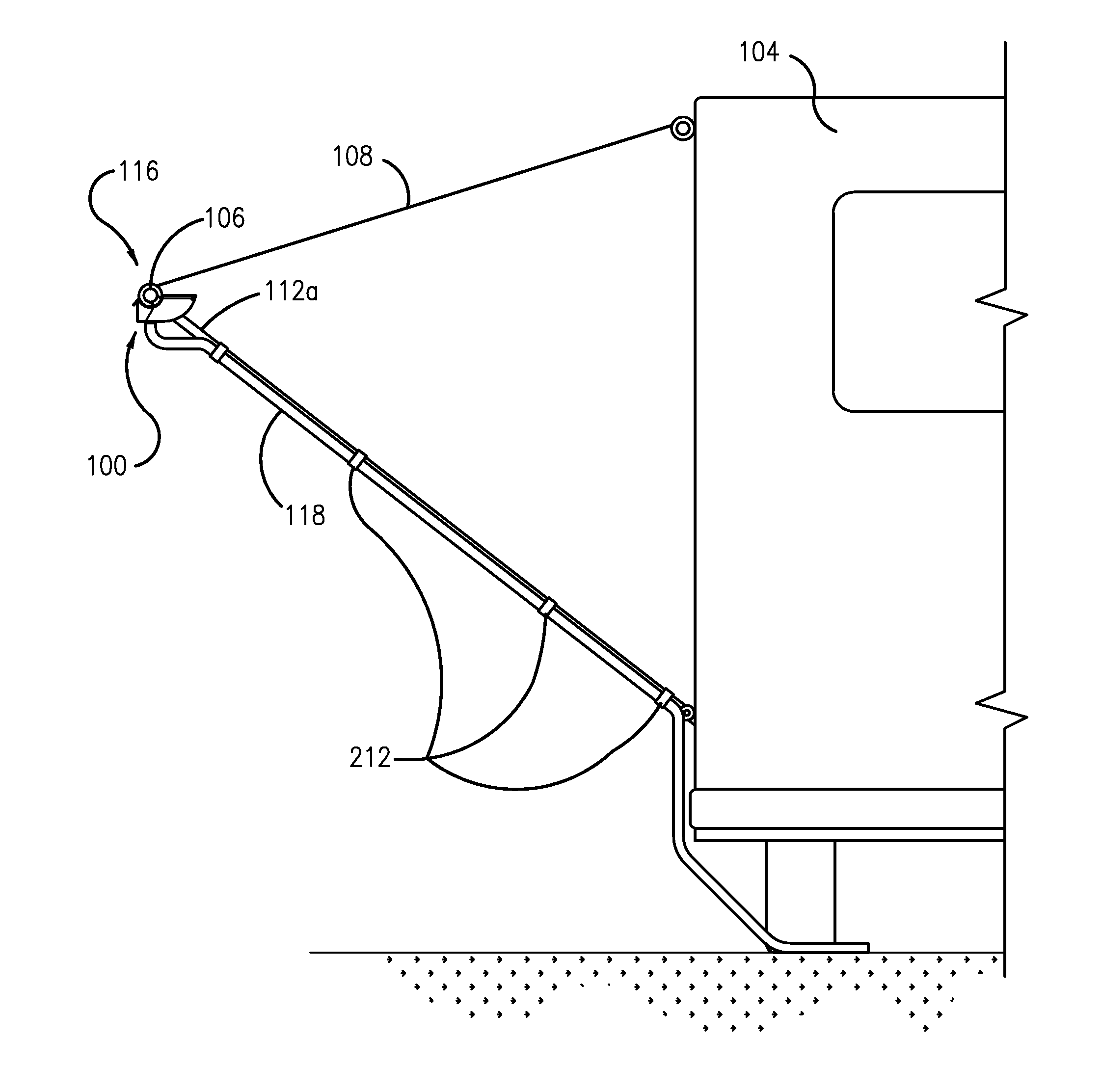
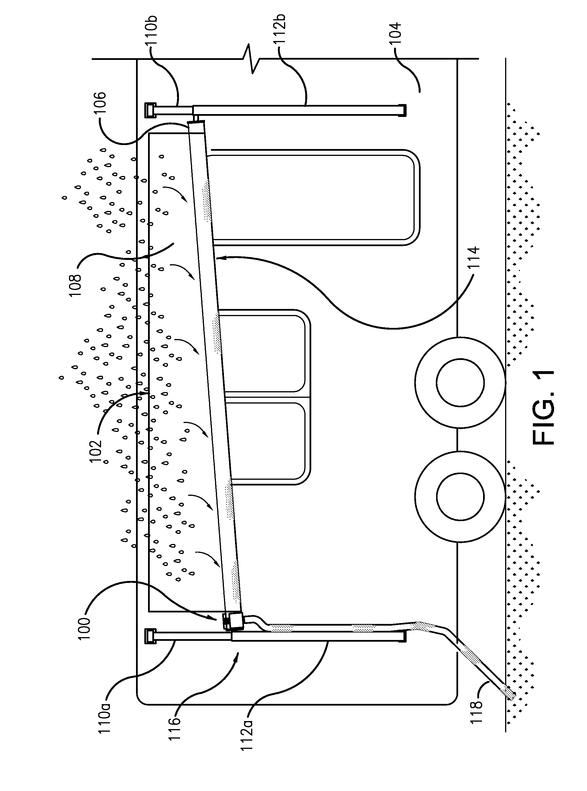
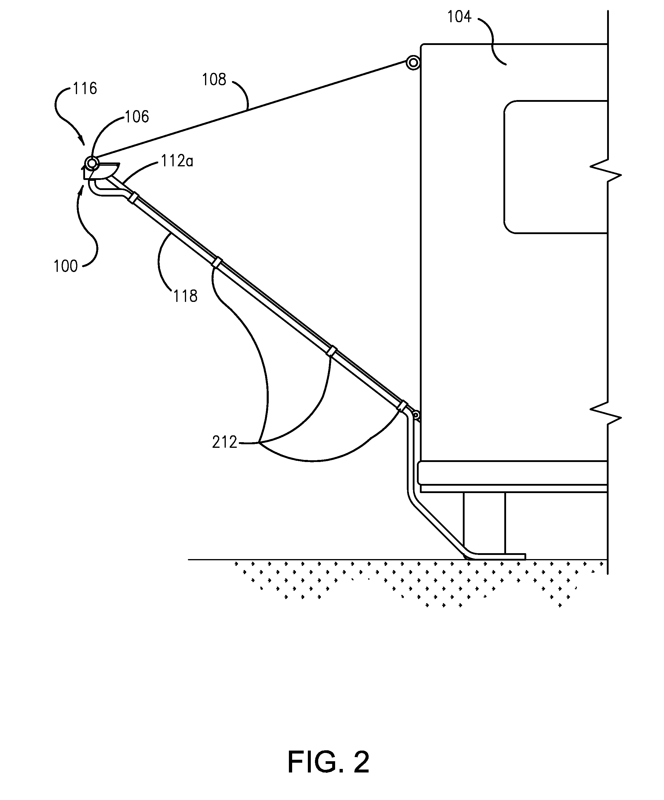
[0025]FIG. 1 is a view from the front of a retractable awning 102 that is attached to and deployed from a recreational vehicle (RV) or camper 104. The retractable awning 102 is attached to RV / camper 104 in a manner that is well known in the art. The retractable awning 102 has a roller tube 106 from which an awning canopy 108 is unrolled when being deployed, or onto which it is rolled when being retracted. The roller tube 106 also acts as an awning beam providing structural support to the leading edge 114 of the awning canopy 108. The awning canopy 108 is supported by bracing members 110a and 110b, which run parallel with the outside edges of the awning canopy 108 to provide rigidity to the canopy 108 when it is fully extended. The retractable awning 102 also includes support members 112a and 112b that support the leading edge 114 and awning beam 106 of the retractable awning 102.

[0026]As illustrated in FIG. 1, one of the support members 112a is deployed such that it is shorter than ...


PUM


Abstract

A rain catch is disclosed that collects and diverts rainwater from the perimeter of a retractable awning having an awning canopy that is tilted so as to have a lowest corner. The rain catch has a body that includes a body cavity and an awning beam collar, the body cavity having an opening that receives rainwater flowing off the lowest corner of the awning canopy. The awning beam collar is attached to the awning beam of the retractable awning at the lowest corner of the canopy. The rain catch is attached to the awning beam such that the opening of the collector body cavity is disposed in a space between the edge of the awning canopy and a bracing member at the lowest corner of the awning. The rain catch can include an extended downspout coupled to the downspout port to direct received rainwater away from the retractable awning.

Description

FIELD OF THE INVENTION[0001]This invention relates to rainwater capture and diversion, and more particularly to rainwater capture and diversion as applied to awnings.BACKGROUND OF THE INVENTION[0002]The use of retractable awnings has become widespread. They are commonly used to provide shelter from the elements for outdoor spaces such as patios. They can also be employed to lower energy bills by shading windows of dwellings, and are widely installed on campers and motor homes to provide protection from the elements for a patio area immediately adjacent thereto. Their retractable design is particularly important to the camper and mobile home application as it is critical that they be easily stowed while the camper or mobile home is in motion.[0003]One important concern users of awnings have, both fixed and retractable, is control of rainwater as it sheds from the top surface of the awning. Awnings are typically deployed such that their top surfaces are declined at a downward angle fr...

Claims


Application Information

Patent Timeline
Patent Type & Authority Patents(United States)
IPC IPC(8): E04D13/00
CPCE04F10/0614E04F10/0625E04F10/0692Y10T137/9464
Inventor ZIEGLER, TOM
Owner ZIEGLER TOM
Learn More