Tube for an observation device

a technology of observation device and tube, which is applied in the field of tubes for observation devices, can solve the problems of high mechanical expenditure of the optical correction mechanism comprised of swung-in or pushed-in lenses, clear higher structural volume, and difficult to achieve the effect of reducing the size of the structur

Active Publication Date: 2013-09-24
CARL ZEISS MEDITEC AG
View PDF15 Cites 1 Cited by
  • Summary
  • Abstract
  • Description
  • Claims
  • Application Information

AI Technical Summary

Benefits of technology

The invention is a tube for an optical observation device, such as a microscope, that has a viewing level that is linearly variable in length and / or height. The tube has an optical light path, in which at least two optical elements are disposed. The optical elements can move independently of each other in the optical light path. The tube can also be adjusted in its mechanical length. The invention provides for greater flexibility and precision in optical observation and can be used in various configurations and with different numbers of optical elements.

Problems solved by technology

The high mechanical expenditure for the optical correction mechanism comprised of swung-in or pushed-in lenses must be viewed as an essential disadvantage of EP 1 233 294 B1.
The space required for this is also problematical, since it leads to a clearly higher structural volume.
This swinging range that can be executed, however, is insufficient for many applications.
Among other things, this means that the distance to the microscope axis is too short.

Method used


Image

  • Tube for an observation device
  • Tube for an observation device
  • Tube for an observation device

Examples


Embodiment Construction

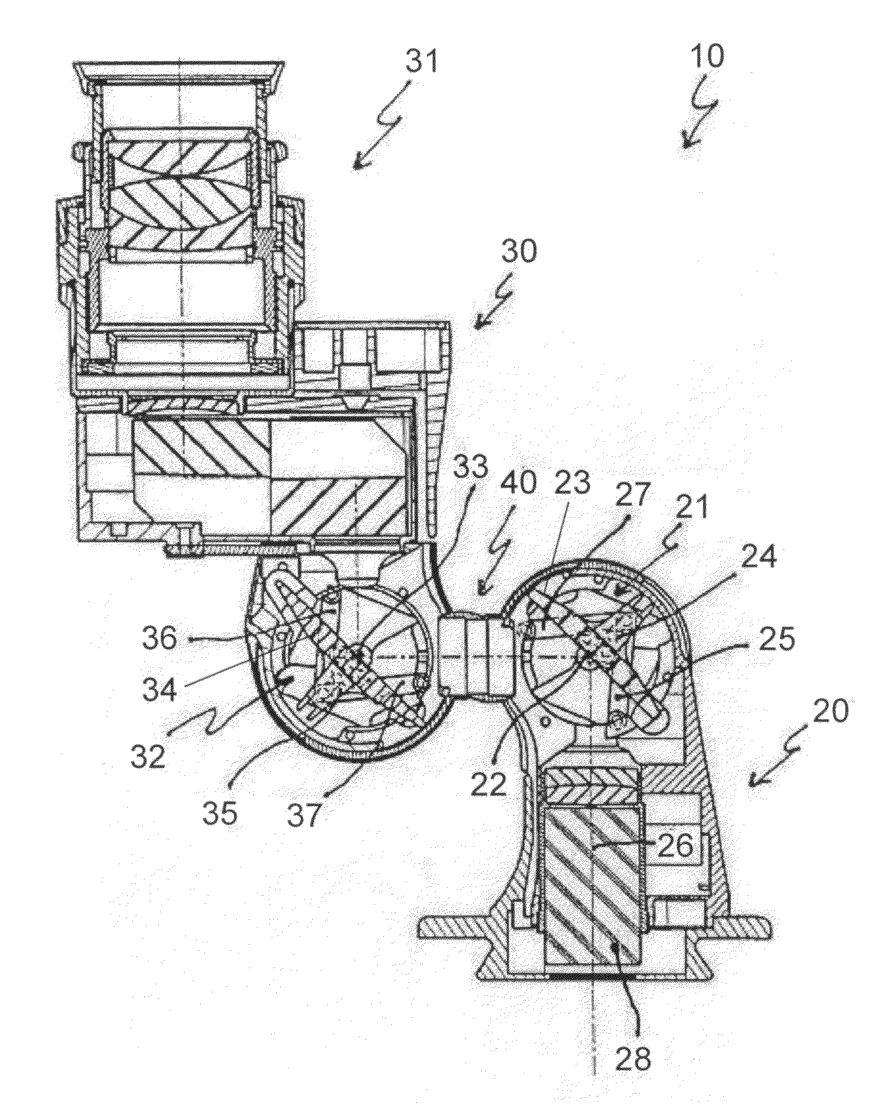
[0067]In the figures, a tube is shown, which is designed as a swing-in tube 10, and which can be used for an optical observation device, for example, a microscope, e.g., an operating microscope.

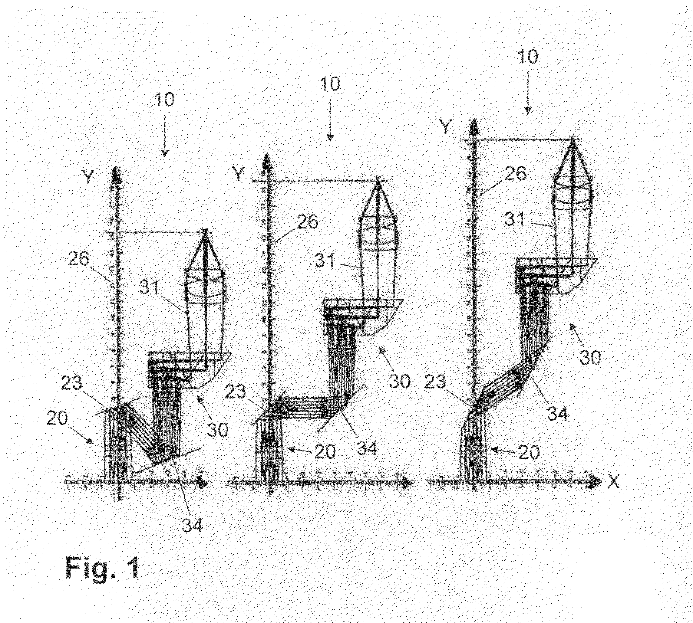
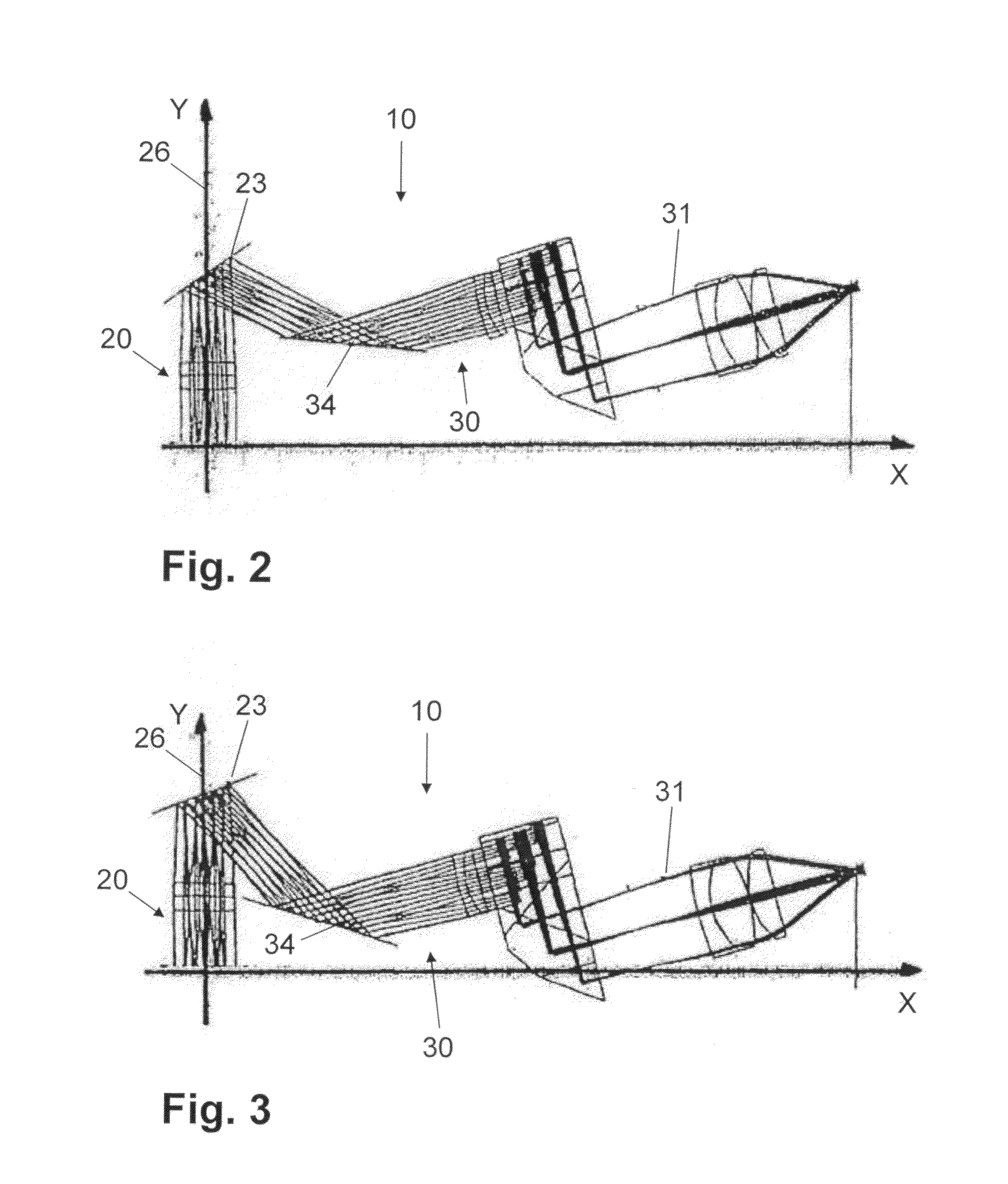
[0068]The swing-in tube 10, which is shown in FIGS. 1 to 5, provides a base part 20, in which a deflecting element 23 disposed in a rotatable manner around an axis of rotation is provided in the form of a tilted mirror. In addition, an eyepiece support 30 with an uptake 31 for the eyepiece is provided, wherein eyepiece support 30 also has a deflecting element 34 in the form of a tilted mirror which is disposed in a rotatable manner around an axis of rotation. The two tilted mirrors 23, 34 are both disposed in a translatory as well as a rotational manner independently of one another, so they can be displaced or rotated.

[0069]The tilted mirrors 23, 34 are turned around the corresponding axes of rotation, which are shown in greater detail in connection with FIGS. 6 to 11. The translatory displac...


PUM


Abstract

A tube for an optical observation device, in particular for a microscope, with a viewing level that is linearly variable in length and / or height, wherein the tube has an optical light path, in which at least two optical elements are disposed, for example, deflecting elements. The tube can be designed, for example, as a swing-in tube, with a base part, wherein a deflecting element is disposed in the base part so that it can rotate around an axis of rotation, and with an eyepiece support that can swing in relative to the base part, wherein a deflecting element is disposed in the eyepiece support so that it can rotate around an axis of rotation. The optical elements may be disposed so that they can move independently of one another in the optical light path.

Description

BACKGROUND OF THE INVENTION[0001]The present invention relates to a tube for an observation device. For example, such an observation device may involve, for example, a microscope or similar device.[0002]In a microscope, for example, an operating microscope, the distance of the object plane from the position of the equipment—exit pupil EP (AP) behind the eyepiece, thus the viewing level or eyepiece height, is determined by the equipment configuration of the system components of the microscope, which is dependent on the respective application.[0003]For ergonomic reasons, of course, an individual adaptation of the viewing level to the body height of the user of the microscope, for example, of a surgeon, is extremely advantageous and thus desirable. In the often time-intensive working with the operating microscope, keeping the body of the surgeon relaxed is a very decisive factor for working without tiring.[0004]In addition, it is a decisive factor not to modify disadvantageously the us...

Claims


Application Information

Patent Timeline
Patent Type & Authority Patents(United States)
IPC IPC(8): G02B21/00A61B19/00G02B21/24
CPCG02B7/001G02B7/24G02B21/0012G02B21/20G02B21/22A61B19/5223G02B21/24A61B90/20
Inventor KOLSTER, NADINEABELE, ALFONSLUECKE, CHRISTIAN
Owner CARL ZEISS MEDITEC AG
Why Eureka
Try Eureka