Adaptive data rate control

a data rate and data technology, applied in the field of adaptive data rate control, can solve the problems of deteriorating communication link, insufficient to achieve smooth operation of wireless mri system, and simply losing acquired mr data, so as to achieve the effect of improving performan

Active Publication Date: 2013-10-01
KONINK PHILIPS ELECTRONICS NV
View PDF23 Cites 8 Cited by
  • Summary
  • Abstract
  • Description
  • Claims
  • Application Information

AI Technical Summary

Benefits of technology

[0007]It is an object of the present invention to provide an adaptive data rate control yielding an improved performance with an available communication link.
[0008]Accordingly, in a first aspect of the present invention a device is presented. The device comprises an acquisition unit configured to acquire examination data, a communication unit configured to transmit the examination data via a communication link and receive control information via the communication link, and an adaptation unit configured to adapt a data rate of the examination data, based on an available quality of service of the communication link, wherein the acquisition unit and / or the adaptation unit is configured to be controlled based on the control information. Thus, a data rate as high as possible for given communication conditions can be achieved. Hence, an improved performance may be attained with an available communication link. That is, the data transmission for an actual available quality of service can be optimized. Further, there is no need to abort an acquisition procedure under bad communication conditions. In addition, a remote control of the device and its acquisition unit and / or adaptation unit over some kind of network is enabled, for example by means of a central control unit transmitting control information via a wireless transport medium.

Problems solved by technology

In addition, noise from other (or own) equipment may temporarily degrade the communication link as well.
However, this may still not suffice to achieve a smooth operation of a wireless MRI system.
Acquired MR data should leave the MRI coil as soon as possible after acquiring it, since storing the MR data would require huge amounts of power-dissipating and volume-consuming memory at the MRI coil.
Further, with the currently available wireless technologies a performance of the communication link can drop below a certain minimum threshold at some points in time, after which the acquired MR data are simply lost.
This is not acceptable from a MRI perspective.

Method used


Image

  • Adaptive data rate control
  • Adaptive data rate control
  • Adaptive data rate control

Examples


Embodiment Construction

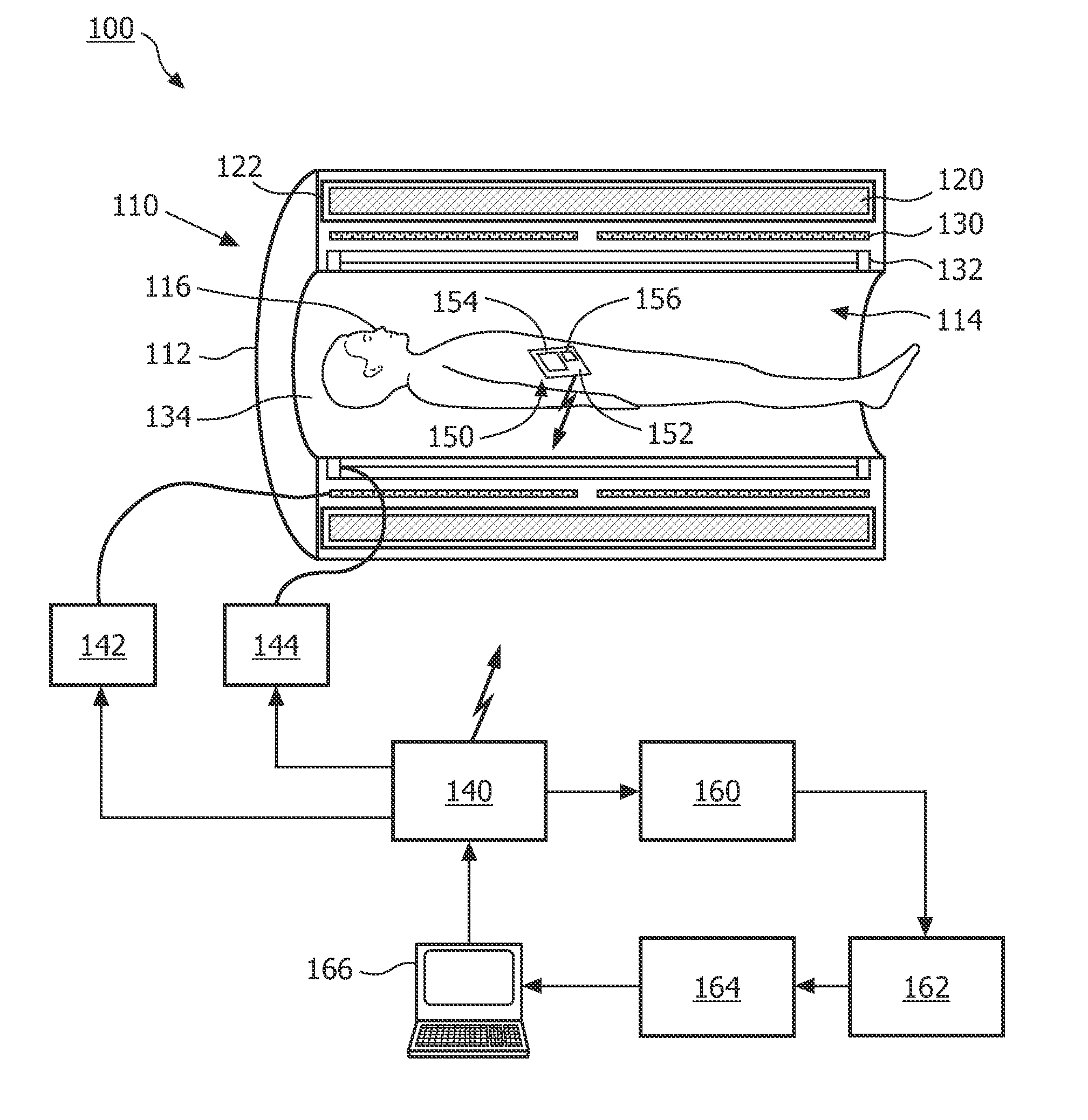
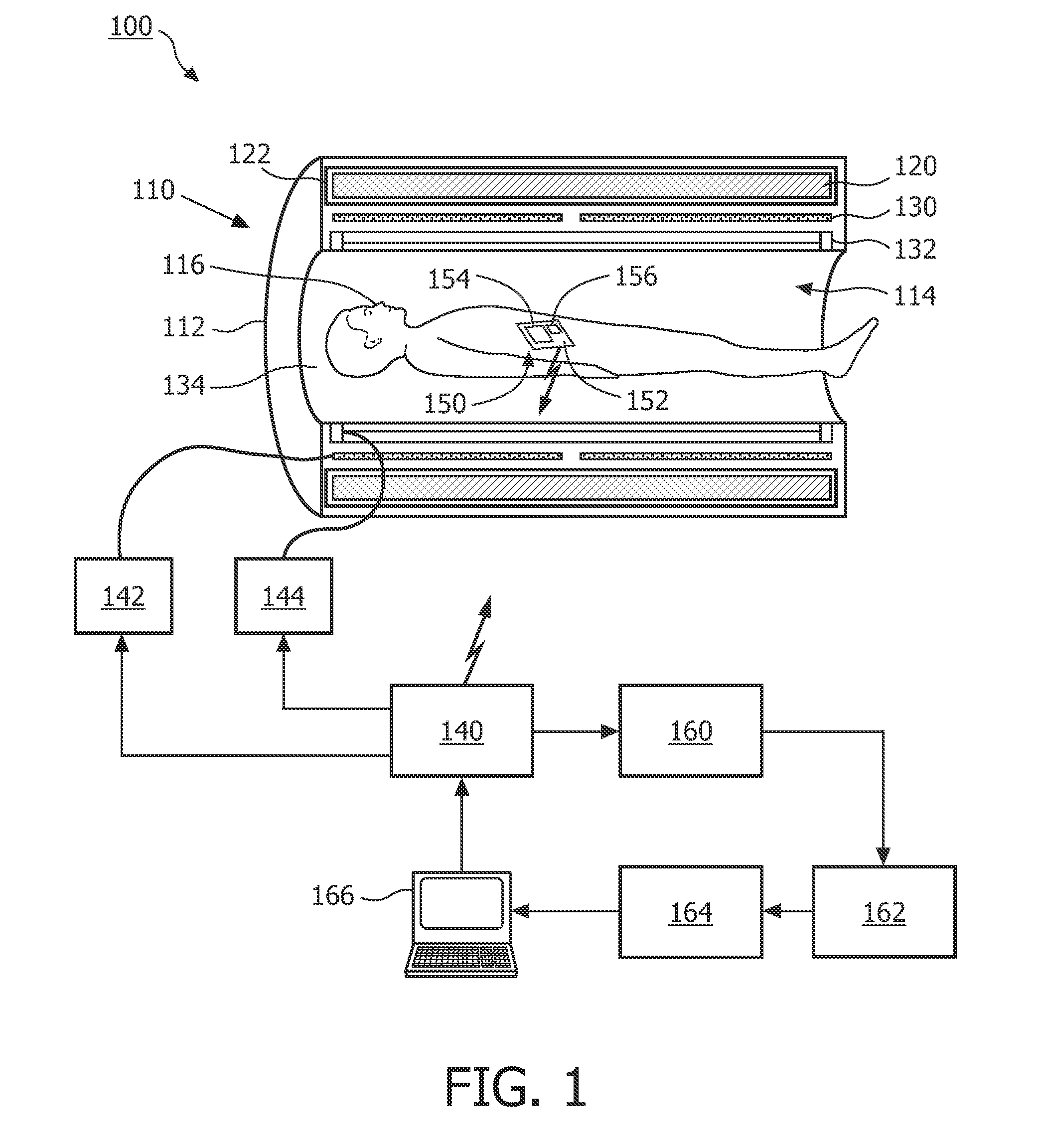
[0029]FIG. 1 shows a schematic diagram illustrating a basic arrangement of an exemplary system 100 according to the embodiment. A magnetic resonance imaging (MRI) system is depicted in FIG. 1. However, the following description is to be considered illustrative or exemplary and not restrictive. Other application areas such as alternative kinds of examination or imaging systems like e.g. x-ray systems are possible.

[0030]A MRI scanner 110 can include a housing 112 defining a generally cylindrical scanner bore 114 inside of which an imaging subject 116 like a human or animal body may be disposed. Main magnetic field coils 120 can be disposed inside the housing 112. The main magnetic field coils 120 may be superconducting coils disposed inside a cryoshrouding 122. Resistive main magnets can also be used. The housing 112 may also house or support magnetic field gradient coils 130 for selectively producing magnetic field gradients in the scanner bore 114. The housing 112 can further house ...


PUM


Abstract

A data rate controlling feedback loop evaluates an actual instantaneous available quality of service of a communication link for transmitting data and controls the data rate based on an evaluation result, Feedback control may both be local to a device for acquiring examination data, such as a magnetic resonance imaging coil, or over the communication link by reducing the data rate at least momentarily to fit the communication link's performance over time, enabling a graceful degradation of an image quality at lower data rates.

Description

FIELD OF THE INVENTION[0001]The present invention generally relates to a device, system, method and computer program for adaptively controlling a data rate based on an available quality of service of a communication link, in particular for use with wireless magnetic resonance imaging (MRI) coils.BACKGROUND OF THE INVENTION[0002]Several manufacturers of MRI systems currently try to develop pure cordless / wireless MRI coils. A prerequisite for such wireless MRI coils is that an analog magnetic resonance (MR) signal (in the case of an analog coil) or acquired MR data (in the case of a digital coil) can be transported to a MR examination system via a high-speed wireless communication link.[0003]A wireless communication link has a certain quality of service (QoS) with respect to latency and bandwidth properties of such a link. In real life, a performance of a wireless data transport depends to a large extent on an actual transfer response of a wireless channel used to perform the data tra...

Claims


Application Information

Patent Timeline
Patent Type & Authority Patents(United States)
IPC IPC(8): A61B5/05
CPCG01R33/3621H04L1/0006G06F19/321G01R33/3692G16H30/20
Inventor SAES, MARC PAULVAN LIERE, FILIPSVAN HELVOORT, MARINUS JOHANNES ADRIANUS MARIA
Owner KONINK PHILIPS ELECTRONICS NV
Why Eureka
Try Eureka