Supercharge Your Innovation With Domain-Expert AI Agents!

Dummy hard disk drive

a hard disk drive and a sleeve technology, applied in the direction of instruments, paper/cardboard articles, electrical apparatus casings/cabinets/drawers, etc., can solve the problem of space was

Inactive Publication Date: 2013-10-08
HON HAI PRECISION IND CO LTD
View PDF5 Cites 0 Cited by
  • Summary
  • Abstract
  • Description
  • Claims
  • Application Information

AI Technical Summary

Benefits of technology

Enables efficient space utilization during transportation and storage by folding into the smallest possible space while maintaining structural integrity against collisions and mishandling, ensuring safe and space-efficient packaging.

Problems solved by technology

However, a traditional dummy HDD is often a fixed structure, and not foldable, which causes a waste of space when the dummy HDD is boxed and transported.

Method used


Image

  • Dummy hard disk drive
  • Dummy hard disk drive
  • Dummy hard disk drive

Examples


Embodiment Construction

[0014]The disclosure, including the accompanying drawings, is illustrated by way of examples and not by way of limitation. It should be noted that references to “an” or “one” embodiment in this disclosure are not necessarily to the same embodiment, and such references mean at least one.

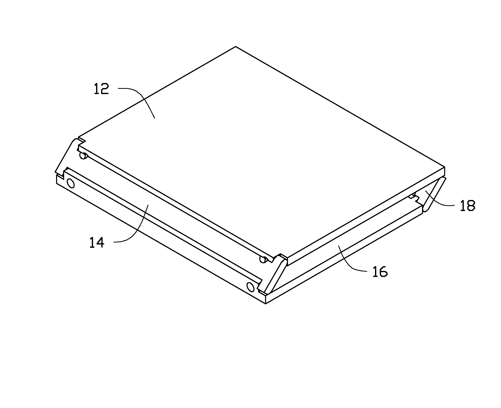
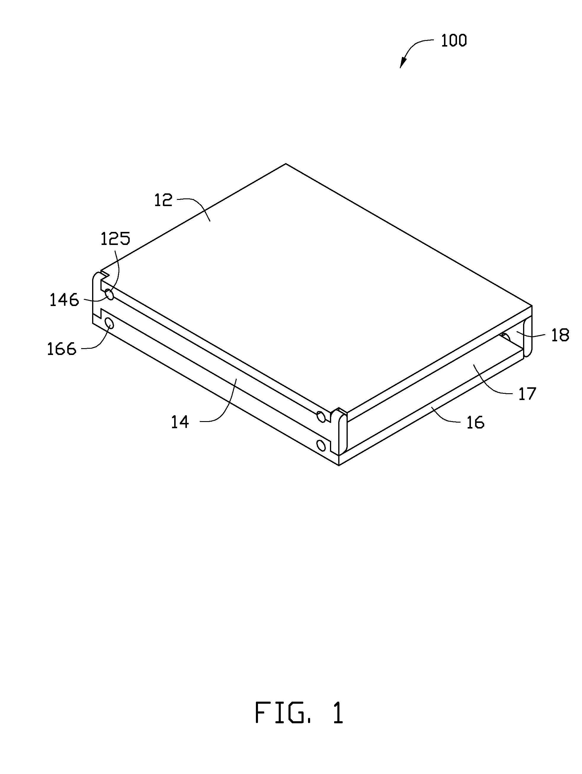
[0015]Referring to FIG. 1, an embodiment of a dummy hard disk drive (HDD) 100 includes a top plate 12, a first side plate 14, a bottom plate 16, and a second side plate 18. The top plate 12 is parallel to the bottom plate 14. The length and width of the top plate 12 and the bottom plate 16 are the same as those of an actual HDD. The first side plate 14 is parallel to the second side plate 18. The top plate 12, the first side plate 14, the bottom plate 16, and the second side plate 18 are made of resilient material, such as rubber or plastic.

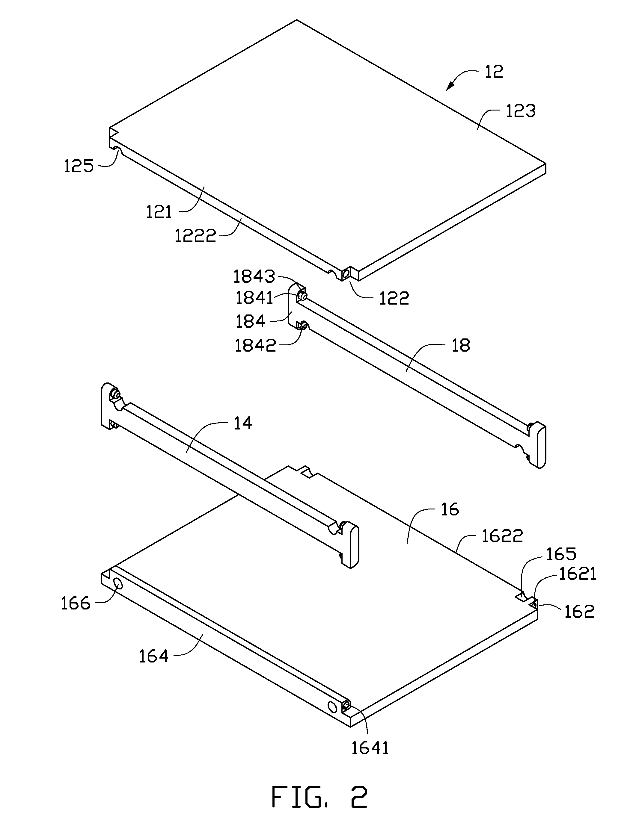
[0016]Referring to FIGS. 2-5, two cutouts 122 are defined in opposite ends of a first side 121 of the top plate 12. The first side 121 forms a flange 1222 between ...


PUM


Abstract

A dummy hard disk drive (HDD) is for arrangement in an electronic device. The dummy HDD includes a top plate, a first side plate, a bottom plate, and a second side plate which can be formed into either a rigid box, or into a thick flat plate.

Description

CROSS-REFERENCE TO RELATED APPLICATION[0001]Relevant subject matter is disclosed in a pending U.S. patent application with application Ser. No. 13 / 221,857, filed on Aug. 30, 2011 and entitled “DUMMY HARD DISK DRIVE”, which is assigned to the same assignee as this patent application.BACKGROUND[0002]1. Technical Field[0003]The present disclosure relates to a dummy hard disk drive (HDD) for an electronic device.[0004]2. Description of Related Art[0005]An electronic device, such as a computer or a server, usually includes a plurality of brackets for mounting HDDs. A dummy HDD is usually fitted in each bracket to avoid the bracket from being deformed or damaged when manufacturing or transporting these brackets. When a real HDD is received in the bracket, the dummy HDD will be taken out. However, a traditional dummy HDD is often a fixed structure, and not foldable, which causes a waste of space when the dummy HDD is boxed and transported.BRIEF DESCRIPTION OF THE DRAWINGS[0006]Many aspects...

Claims


Application Information

Patent Timeline
Patent Type & Authority Patents(United States)
IPC IPC(8): G06F1/16H05K5/00H05K7/00
CPCG06F1/187
Inventor SUN, ZHENG-HENG
Owner HON HAI PRECISION IND CO LTD
Features
  • R&D
  • Intellectual Property
  • Life Sciences
  • Materials
  • Tech Scout
  • Unparalleled Data Quality
  • Higher Quality Content
  • 60% Fewer Hallucinations
Learn More