Method and apparatus for elimination of duplexers in transmit/receive phased array antennas

a phased array, transmit/receive technology, applied in the field of closeness, can solve the problems of physical inability to place circulators or transmit/receive switches at each of the antenna feeds of dipoles, duplexers in the form of circulators and t/r switches are much too large to be placed at the feedpoint of dipoles, etc., to achieve the effect of simplifying design requirements, allowing flexibility in antenna design, and eliminating bulky and lossy components

Active Publication Date: 2013-10-15
BAE SYST INFORMATION & ELECTRONICS SYST INTERGRATION INC
View PDF7 Cites 2 Cited by
  • Summary
  • Abstract
  • Description
  • Claims
  • Application Information

AI Technical Summary

Benefits of technology

[0015]The result is that one can provide minimal electronics at the feedpoints of the dipole or adjacent dipole ends above the ground plane such that one can have very large numbers of transmit / receive elements in a planar array and switch the array between transmit and receive modes without the use of duplexers, either in the form of circulators or DPDT T / R switches. Moreover, state switches employ minimal electronics making them deployable at the spaced-apart ends of opposed λ / 4 dipole elements. Thus, the present invention eliminates the need to have either a circulator or a transmit / receive switch at a dipole feed by separating the points at which one places the transmit and receive elements. No longer is the dipole feedpoint used for both transmit and receive functions.
[0017]As a result of locating state switches at various points one has achieved considerable flexibility since one can separate out the transmit and receive functions by simply distributing the transmit and receive elements and controlling associated state switches.
[0021]In summary, the replacement and elimination of duplexers in a tightly coupled dipole phased array starts with transmit and receive functions physically separated and having different antenna port feeds. The simple coupling network used with tightly coupled dipole arrays is replaced by a state switch which alternates between a coupling state and a dipole feed connection state. The basic method can be applied to antenna apertures of various kinds, including both linear and dual polarized versions. The ability to locate state switches at various nodes in tightly coupled dipole phased arrays permits flexibility in antenna design and eliminates bulky and lossy components, simplifies the design requirements and allows independent optimization of the components.

Problems solved by technology

However, when it is intended for these antennas to be driven in the transmit and receive modes alternately, placing a circulator or transmit / receive switch at each of the antenna feeds for the dipoles can be physically impossible, depending on frequency of operation, due to the limitations of the physical size of such circulators and switches which precludes their use above the ground plane normally used for such planar arrays.
For instance, circulators tend to be too large at the frequencies of interest.
Duplexers in the form of circulators and T / R switches are much too large to be placed at the feedpoint of a dipole, especially when these duplexing units are above the ground plane for the planar array.
Moreover, the typical circulators are bandwidth-limited and TR switches have excessive losses.
Thus T / R switches absorb power during the transmission process and limit sensitivity on the receive side.
Note also that any piece of electronics that is interposed between the receiver or transmitter and the antenna will have parasitics that will limit the bandwidth.
Moreover, circulators get bulkier and lossier as one seeks to achieve a 5:1 bandwidth.
Thus, using a circulator limits the bandwidth performance.
On the other hand, transmit / receive switches with pin diodes result in unacceptable losses that limit performance.
Moreover, dipoles require balanced inputs and the use of baluns to convert an unbalanced line to a balanced line is undesirable due to the added parasitics and losses.
Two other factors which further complicate phased array implementations of circulators include the use of high field strength bias magnets which must be shielded to prevent interaction with the shielding significantly adding to the bulk of the structure.
The use of baluns adds additional circuitry which further degrades performance in terms of loss, match and bandwidth.
Such weight and size limitations as well as limitations on performance are particularly acute when, for instance, planar arrays of miniature dipoles exceed 1,000×1,000 dipole arrays or greater.

Method used


Image

  • Method and apparatus for elimination of duplexers in transmit/receive phased array antennas
  • Method and apparatus for elimination of duplexers in transmit/receive phased array antennas
  • Method and apparatus for elimination of duplexers in transmit/receive phased array antennas

Examples


Embodiment Construction

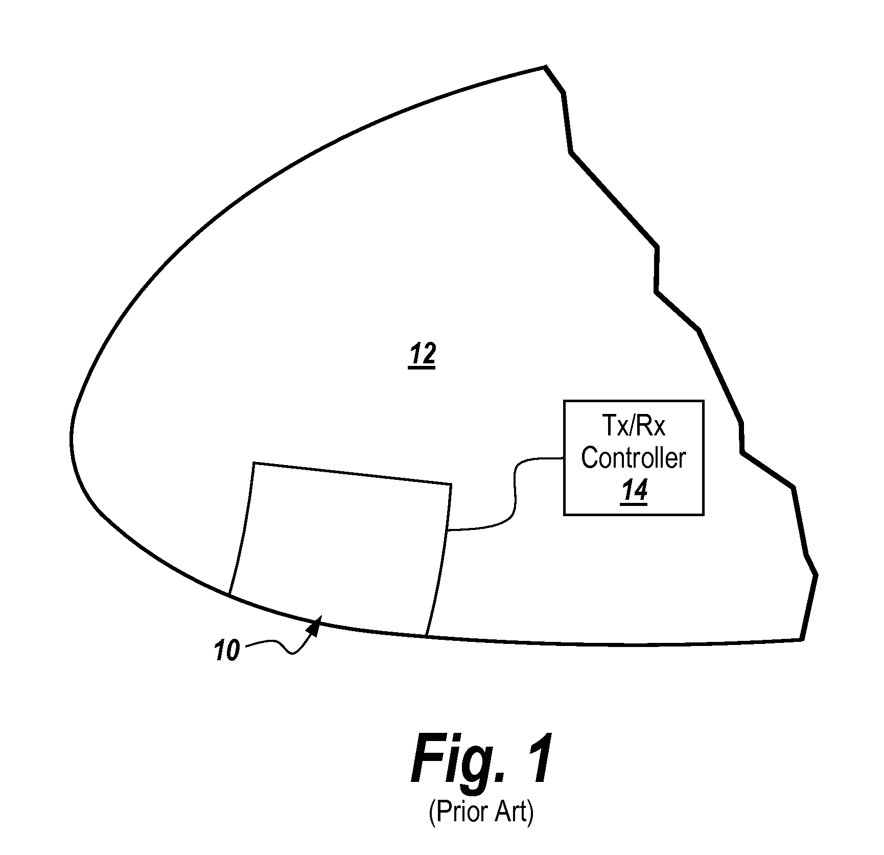
[0047]As shown in U.S. Pat. No. 6,512,487, a wideband phased array antenna 10 is mounted to the nose cone of an aircraft 12 or other rigid mounting member having a non-planar three dimensional shape. As shown, the array is connected to a transmit / receive controller 14 for alternately driving the antenna or receiving signals.

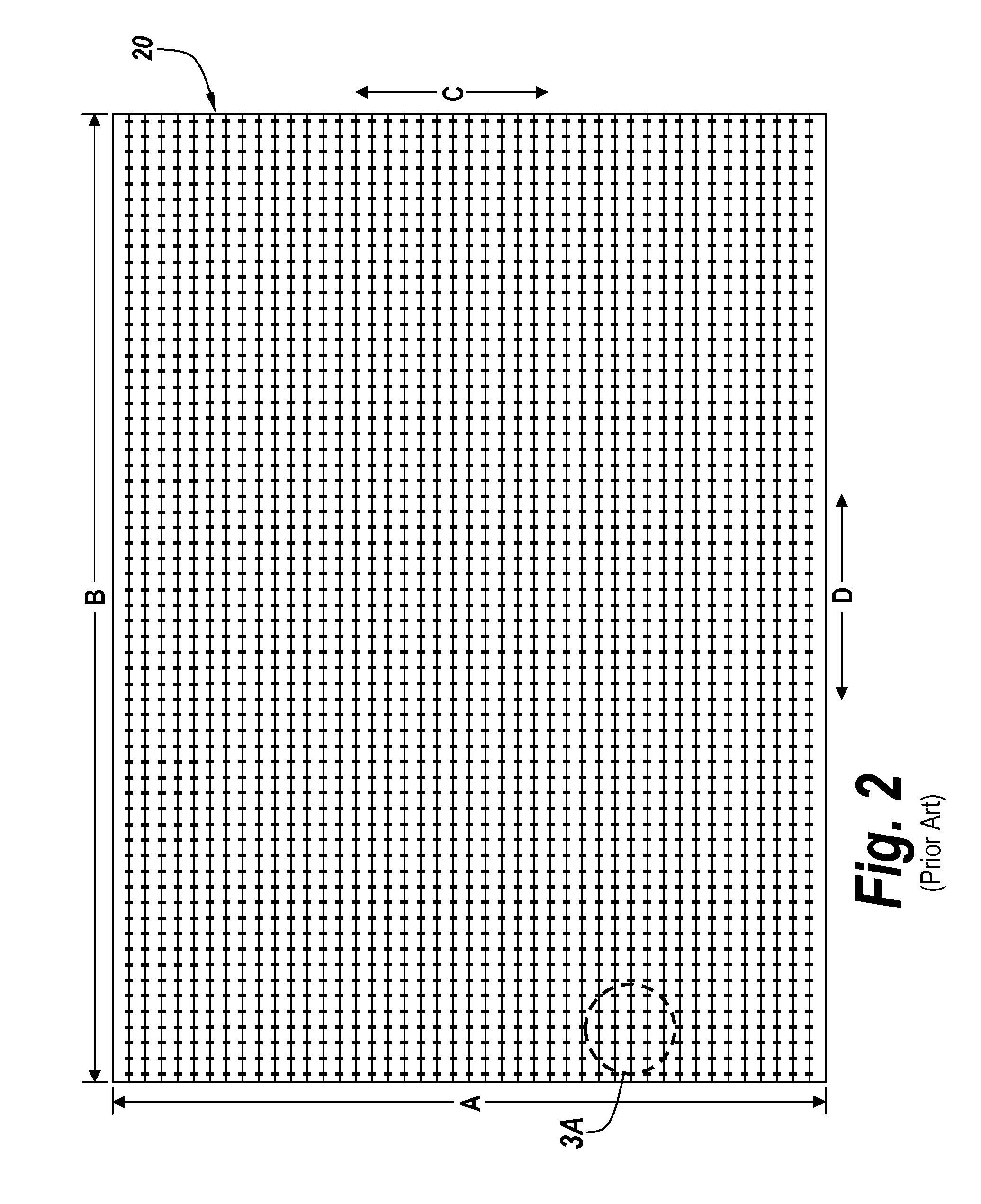
[0048]This array is a closely or tightly coupled dipole array such that as shown in FIG. 2 there is a dipole layer 20 which in one embodiment is comprised of a conductive layer having an array of dipole elements printed thereon. As can be seen by the exploded view of FIG. 3 each of the dipole elements 40 includes a feed 42 between adjacent dipole ends 44.

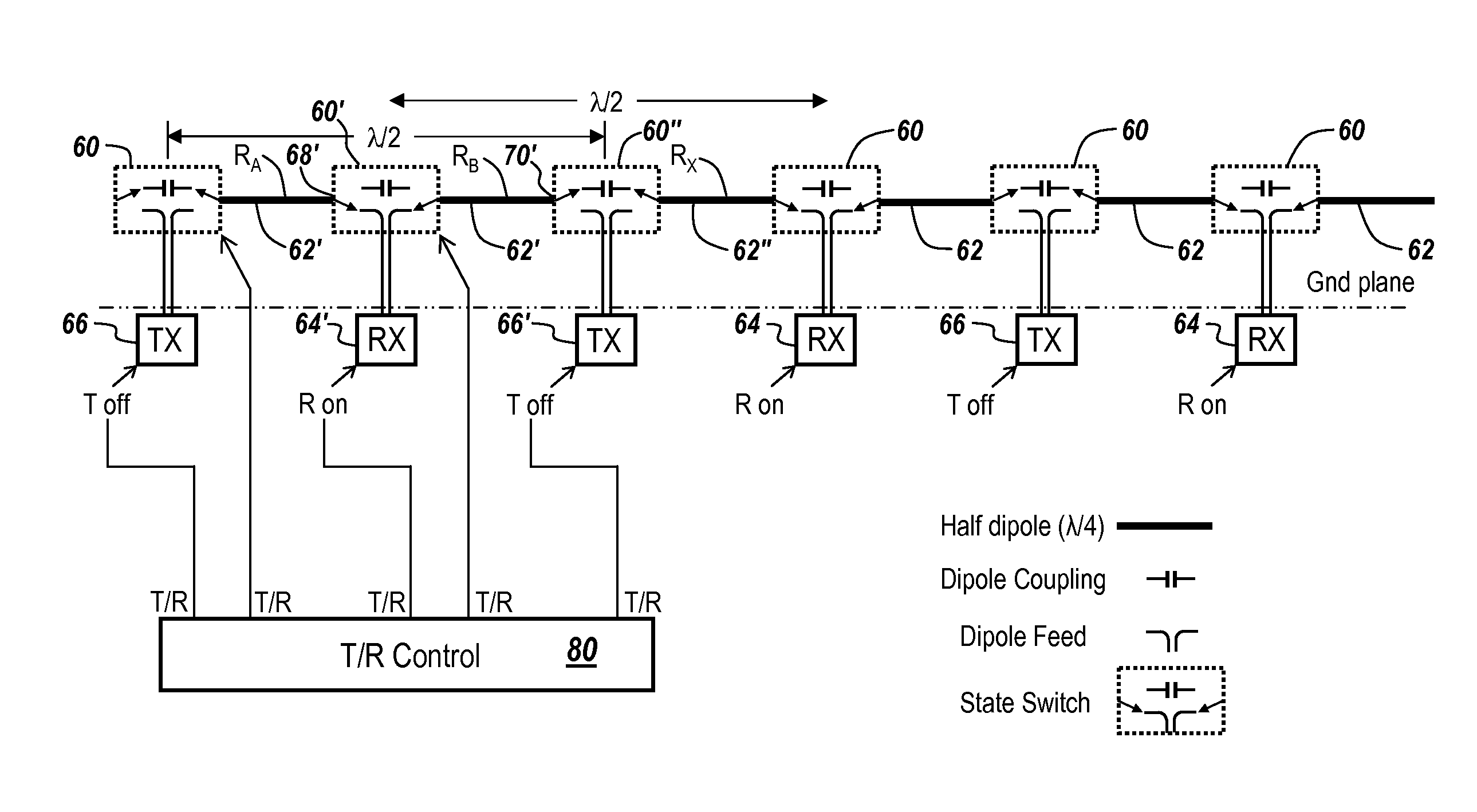
[0049]As shown in FIG. 4, the array requires isolation of the transmitter from the receiver. Here, dipole elements 44 are connected to a circulator 46 which couples transmit element 48 to dipole 44 during a transmit mode, and receive element 50 to the dipole elements during a receive mode. This constitutes one em...


PUM


Abstract

The replacement and elimination of duplexers in a tightly coupled dipole phased array starts with transmit and receive functions physically separated and having different antenna port feeds. The simple coupling network used with tightly coupled dipole arrays is replaced by a state switch which alternates between a coupling state and a dipole feed connection state. The basic method can be applied to antenna apertures of various kinds, including both linear and dual polarized versions. The ability to locate state switches at various nodes in tightly coupled dipole phased arrays permits flexibility in antenna design and eliminates bulky and lossy components, simplifies the design requirements and allows independent optimization of the components.

Description

RELATED APPLICATIONS[0001]This application claims rights under 35 USC §119(e) from U.S. Application Ser. No. 61 / 328,693 filed Apr. 28, 2010, the contents of which are incorporated herein by reference.FIELD OF THE INVENTION[0002]This invention relates to closely or tightly coupled dipole arrays and more particularly to a method and apparatus for elimination of duplexers in transmit / receive phased array antennas.BACKGROUND OF THE INVENTION[0003]As illustrated in U.S. Pat. No. 6,512,487 entitled Wide Band Phased Array Antenna and Associated Methods; U.S. Pat. No. 6,771,221 entitled Enhanced Bandwidth Dual Layer Current Sheet Antenna; U.S. Pat. No. 7,084,827 entitled Phased Array Antenna with an Impedance Matching Layer and Associated Methods; as well as U.S. Pat. No. 6,552,687 entitled Enhanced Bandwidth Single Layer Current Sheet Antenna, arrays of closely or tightly coupled dipole arrays are described. These inventions are based on an invention by Benedict A. Munk described in U.S. P...

Claims


Application Information

Patent Timeline
Patent Type & Authority Patents(United States)
IPC IPC(8): H01Q21/00H01Q3/24
CPCH01Q3/24H01Q21/062
Inventor MEHARRY, DAVID E.LAPIERRE, RANDALL R.SCHMANSKI, BERNARD J.
Owner BAE SYST INFORMATION & ELECTRONICS SYST INTERGRATION INC
Why Eureka
Try Eureka