Methods, devices, and systems for non-mechanically restricting and/or programming movement of a tool of a manipulator along a single axis

a technology of manipulator and tool, applied in the field of surgical robotics, can solve the problems of creating z-lock conditions through mechanical limitations, affecting the accuracy of manipulators, and the brain is not fixed within the cranial cavity and can shift, and the accuracy of relatively small brain shifts is problemati

Active Publication Date: 2013-10-15
DEERFIELD IMAGING INC
View PDF22 Cites 206 Cited by
  • Summary
  • Abstract
  • Description
  • Claims
  • Application Information

AI Technical Summary

Problems solved by technology

Current procedures using frame-based or frameless stereotactic tools create Z-lock conditions through mechanical limitations.
However, the brain is not fixed within the cranial cavity and can shift as a result of damage, tumours, hydration, and body position changes.
These relatively small brain shifts can be problematic in term of accuracy and pose a safety concern.
Furthermore, in frame-based stereotactic procedures, attachment of a head frame to the patient's head is also required; this is both uncomfortable and time consuming.
This can pose a problem for surgeons who need to be positioned by the head of the patient to navigate stereotactic tools to the target.

Method used


Image

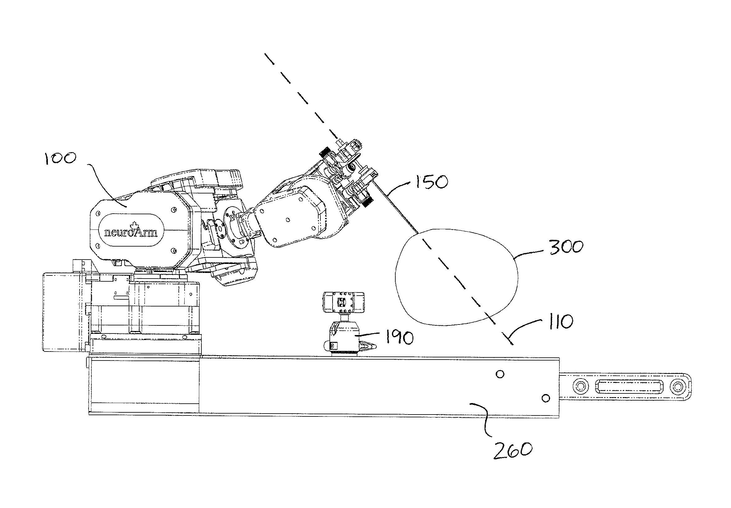
  • Methods, devices, and systems for non-mechanically restricting and/or programming movement of a tool of a manipulator along a single axis
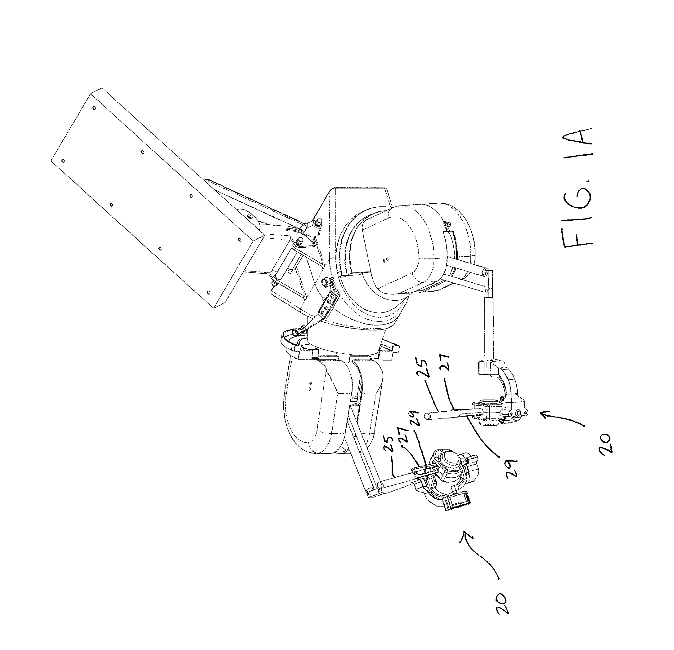
  • Methods, devices, and systems for non-mechanically restricting and/or programming movement of a tool of a manipulator along a single axis
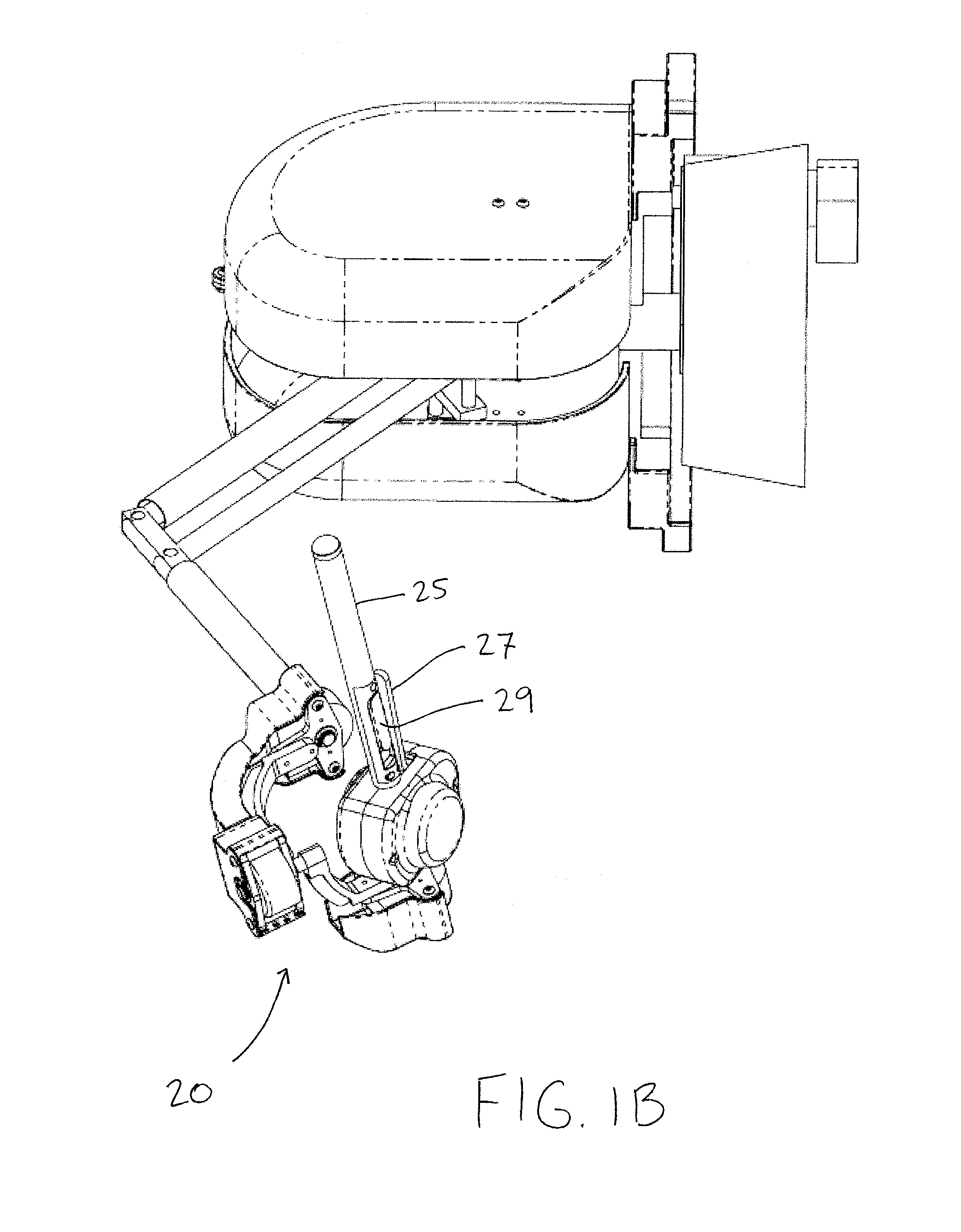
  • Methods, devices, and systems for non-mechanically restricting and/or programming movement of a tool of a manipulator along a single axis

Examples


Embodiment Construction

[0031]The terms “comprise” (and any form of comprise, such as “comprises” and “comprising”), “have” (and any form of have, such as “has” and “having”), “contain” (and any form of contain, such as “contains” and “containing”), and “include” (and any form of include, such as “includes” and “including”) are open-ended linking verbs. As a result, a method, device, or system that “comprises,”“has,”“contains,” or “includes” one or more recited steps or elements possesses those recited steps or elements, but is not limited to possessing only those steps or elements; it may possess (i.e., cover) elements or steps that are not recited. Likewise, an element of a method, device, or system that “comprises,”“has,”“contains,” or “includes” one or more recited features possesses those features, but is not limited to possessing only those features; it may possess features that are not recited. Similarly, a computer readable medium “comprising” (or “encoded with”) machine readable instructions for p...


PUM


Abstract

Methods, devices (such as computer readable media), and systems (such as computer systems) for performing movements of a tool of a medical robot along a single axis that are achieved by electronically limiting the medical robot's movement to produce movement of the tool along the single axis rather than mechanically restricting the medical robot's movement to produce the single axis movement. The tool's movement will be along the single axis even if a user is moving an input device linked to the medical robot in other axes during the single axis movement. In addition, techniques are disclosed for automating the single axis movement such that it can be programmed to stop at a target location and start at or near a second (e.g., starting) location, which is useful for a procedure such as a brain biopsy, breast biopsy or implantation, and such that a user can execute a command instructing the medical robot to perform the movement without the need for the user to manipulate an input device to cause real-time responsive movement of the medical robot.

Description

CROSS REFERENCE TO RELATED APPLICATIONS[0001]This application is a national phase application under 35 U.S.C. §371 of International Application No. PCT / IB2008 / 003323, filed Apr. 16, 2008, which claims priority to U.S. Provisional Patent Application Ser. No. 60 / 912,146, filed Apr. 16, 2007, the entire contents of each of which are incorporated by reference. Co-pending U.S. patent application Ser. No. 12 / 596,418 is also incorporated by reference.BACKGROUND INFORMATION[0002]The present methods, devices, and systems relate generally to the field of surgical robotics, and more particularly to the non-mechanical restriction of a manipulator (e.g., a robotic arm with multiple degrees of freedom) to movement of a tool by the manipulator along a single axis. An example of a procedure that can be carried out according to the present methods, devices, and systems is an automated biopsy. An example of a surgical robot that can be used in a procedure to which the present methods, devices, and sy...

Claims


Application Information

Patent Timeline
Patent Type & Authority Patents(United States)
IPC IPC(8): B25J3/00B25J13/00G06G7/62
CPCA61B19/201A61B19/2203B25J3/04B25J9/1666B25J9/1671A61B19/203A61B19/50A61B19/5212A61B19/56A61B2017/00911A61B2019/2223A61B2019/2276A61B2019/501A61B2019/504A61B2019/507A61B2019/5236G05B2219/36432G05B2219/40128G05B2219/40399G05B2219/40418G05B2219/45117G06F19/3481A61B2034/742A61B2034/101A61B2034/104A61B34/25A61B90/361A61B34/30A61B90/11A61B90/14A61B34/37A61B34/10A61B2034/107A61B2090/374G16H20/40G16H30/40
Inventor GREER, ALEXANDERSUTHERLAND, GARNETTEFIELDING, TIMNEWHOOK, PERRY
Owner DEERFIELD IMAGING INC
Why Eureka
Try Eureka