Visual display of room information

a technology for information displays and rooms, applied in the field of hospital communication systems, can solve problems such as creating certain problems and affecting the comprehension of information, and achieve the effect of facilitating the comprehension of information

Inactive Publication Date: 2013-10-15
TELETRACKING TECH
View PDF17 Cites 14 Cited by
  • Summary
  • Abstract
  • Description
  • Claims
  • Application Information

AI Technical Summary

Benefits of technology

[0007]The present invention, in accordance with at least one presently preferred embodiment, utilizes the capabilities of computer to graphically display selected information in a manner which conveys the information to the nurses and other hospital staff in a form which aids in comprehension of the information. Specifically, the information is preferably conveyed on the patient unit level through the use of the patient unit's floor plan in a graphical seating chart type format. A graphical icon is used to represent each room in the patient unit. Components of the icon indicate key considerations for every bed control or admitting department. Additional information may also be displayed by clicking a component of an icon.

Problems solved by technology

Providing information to nurses and other hospital staff in a location remote from a patient room creates certain problems.
Among the problems is presenting information to the medical professionals in a way that assists them in effectively monitoring the information without increasing their level of stress, which may occur if they feel overwhelmed by the amount of information.

Method used


Image

  • Visual display of room information
  • Visual display of room information
  • Visual display of room information

Examples


Embodiment Construction

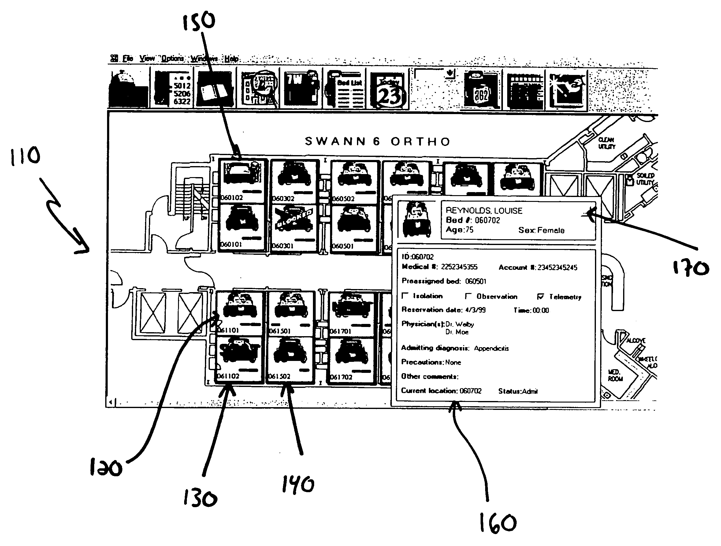
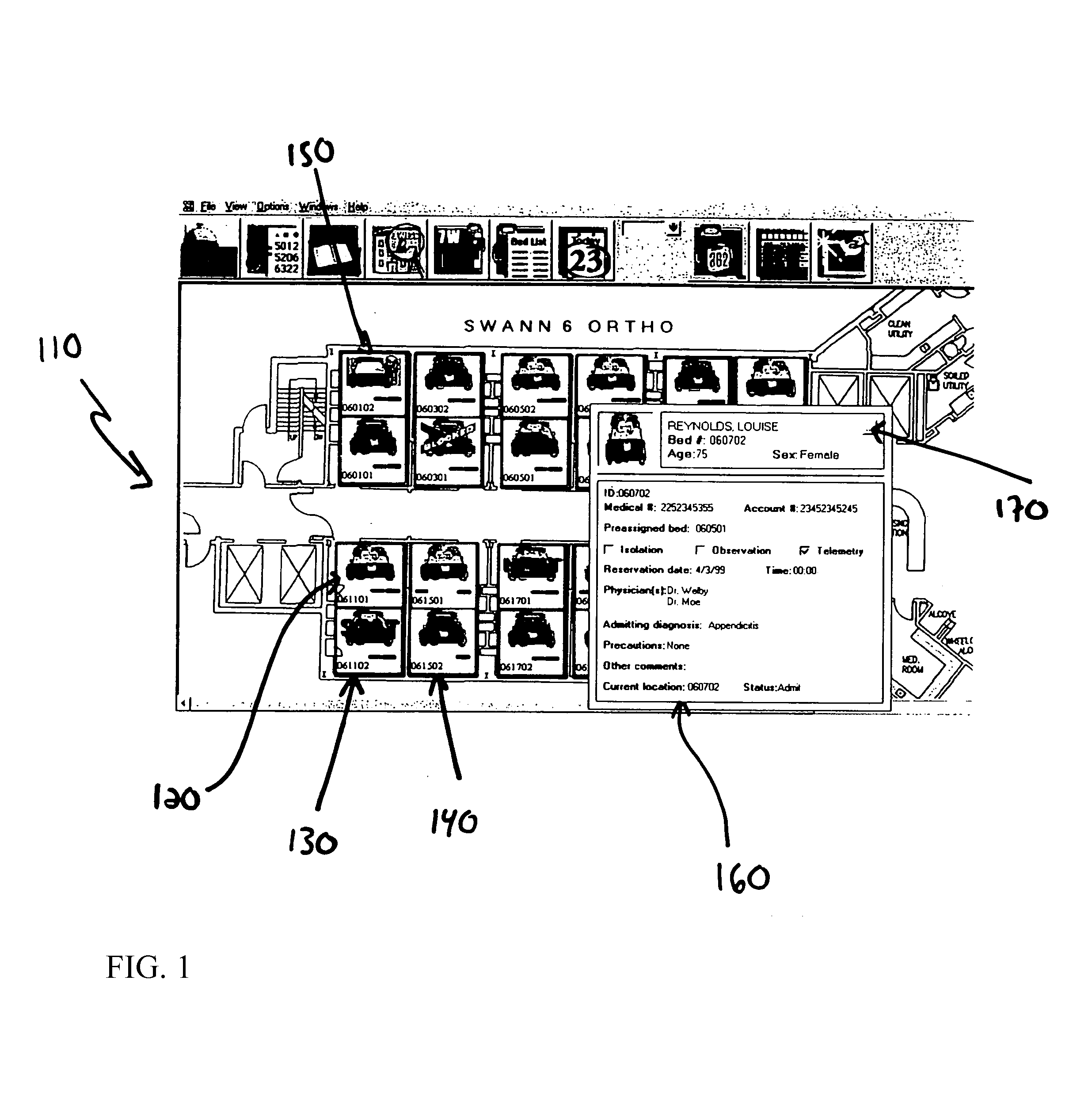
[0016]As shown in FIG. 1, the floor plan 110 of a patient unit within a hospital is shown. An icon visually depicts the status of each room of the patient unit. The preferred components of the icon will be discussed below. To provide an example of the scope of information which is displayed in floor plan 110, however, several of the icons shown in floor plan 110 will now be generally discussed. The icon at reference numeral 120 depicts an occupied room; the icon at reference numeral 130 depicts a room in which an emergency condition exists; the icon at reference numeral 140 depicts an unoccupied room; and the icon at reference numeral 150 depicts a room being cleaned. Important information is thereby visually conveyed to the nurses and other hospital staff in a manner which assists in the comprehension of the information.

[0017]Typically, there is additional information which is useful for the nurses or other hospital staff to have and which is not as important as the information sho...


PUM


Abstract

An apparatus and method for the visual display of room information. Information of interest is graphically displayed in a manner which conveys the information to in a form which aids in comprehension of the information. Specifically, the information is preferably conveyed on the unit level through the use of the unit's floor plan in a graphical seating chart type format. A graphical icon is used to represent each room in the unit. Components of the icon indicate key considerations for every room. Additional information may also be displayed by clicking on a component of the icon.

Description

RELATED APPLICATIONS[0001]This application claims priority from U.S. Provisional Application Ser. No. 60 / 133,524 filed on May 10, 1999, which is hereby incorporated by reference.FIELD OF THE INVENTION[0002]The present invention relates generally to a hospital communication system, and more particularly to an apparatus and method to present patient room information to hospital personnel to enhance comprehension of such information.BACKGROUND OF THE INVENTION[0003]Nurses and other attending staff in a hospital ward or hospital wing work under conditions involving high pressure, stress and long hours. These care givers must remain alert to respond to patient needs, in both emergency and non-emergency situations. Due to economic practicalities and the ever-increasing costs of medical care, it is necessary to make the most efficient use of nurses and staff on call in a hospital ward or hospital wing, particularly at night when nurse and staff levels are maintained at a minimum.[0004]On t...

Claims


Application Information

Patent Timeline
Patent Type & Authority Patents(United States)
IPC IPC(8): G06F17/00G06F17/30
CPCG06F19/327G16H40/20G06F3/04817G06F3/0484G06F21/31
Inventor NACEY, GENE E.
Owner TELETRACKING TECH
Why Eureka
Try Eureka