
Wireless audio transmission system, receiver, video camera and audio mixer

a technology of audio transmission system and receiver, applied in the field of wireless audio transmission system, receiver, video camera and audio mixer, can solve the problems of reducing operability, reporting opportunity may be missed, and reducing operability, and achieve excellent operability and excellent operability

Inactive Publication Date: 2013-10-29
SONY CORP
View PDF21 Cites 0 Cited by
  • Summary
  • Abstract
  • Description
  • Claims
  • Application Information

AI Technical Summary

Benefits of technology

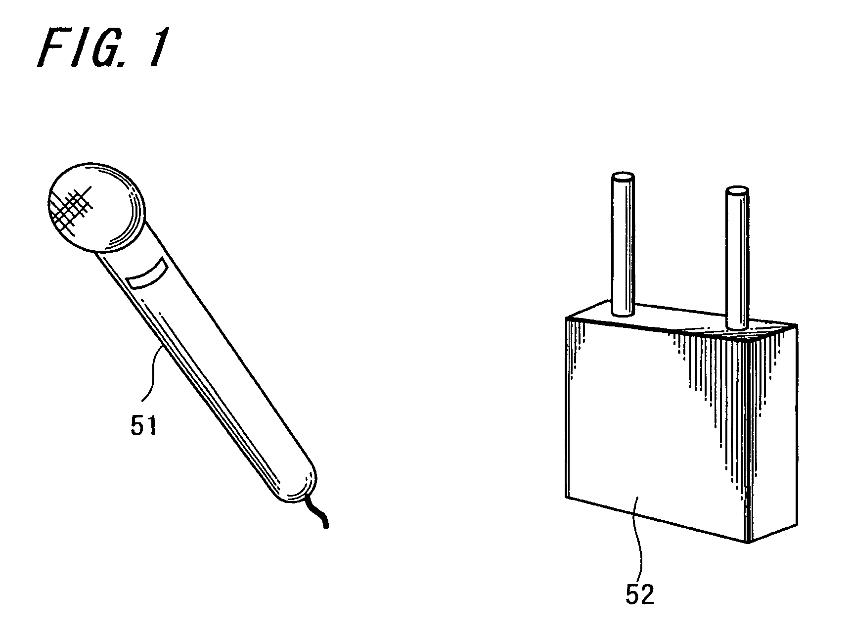
[0014]Here, there is considered a method of quickly setting the frequency, in which a wireless microphone (for example, the receiver 52 in FIG. 1) has the function of automatically detecting available frequencies and the function of displaying information on the detected available frequencies. Hence, the available frequencies are confirmed by viewing this information displayed on the wireless microphone so that the available frequency can be set as the frequency to be used.
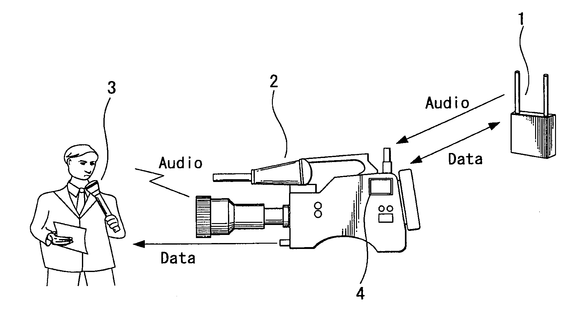
[0019]According to an embodiment of the present invention, there is provided a wireless audio transmission system that includes a transmitter, a receiver and a video camera. The transmitter has a microphone and a modulator-transmitter transmitting a radio wave modulated by an audio signal from the microphone. The receiver has a receiver-demodulator demodulating the audio signal after receiving the radio wave transmitted from the transmitter and outputs the audio signal demodulated by the receiver-demodulator to the outside of the receiver. The audio signal output from the receiver is input to the video camera. Further in this wireless audio transmission system, the receiver has a detector detecting frequencies of a radio wave not being used by other devices based on a reception level of the radio wave received by the receiver-demodulator and outputs available frequency information indicating the frequencies detected by the detector to the video camera. In addition, the video camera has a controller causing the available frequency information input from the receiver to be displayed on a display unit attached to the video camera.
[0024]Further, the video camera and audio mixer causes the available frequency information input from the wireless microphone to be displayed on display units attached to the video camera and audio mixer.
[0025]Therefore, a camera operator can confirm the available frequencies by viewing the information displayed on that video camera, and an operator operating the audio mixer can confirm the available frequencies by viewing the information displayed on that audio mixer.
[0026]Accordingly, the camera operator and operator of the audio mixer can set the frequency to be used by the wireless microphone after the available frequencies are confirmed under excellent operability.
[0027]According to the embodiments of the present invention, such effectiveness is obtained that the available frequency is confirmed and the frequency to be used by the wireless microphone can be set under excellent operability in the audio transmission system in which the audio signal is input from the wireless microphone into the video camera and audio mixer for audio recording.

Problems solved by technology

Due to this, there is a possibility that a reporting opportunity might be missed particularly when mobility is required, for example, at the time of news coverage.
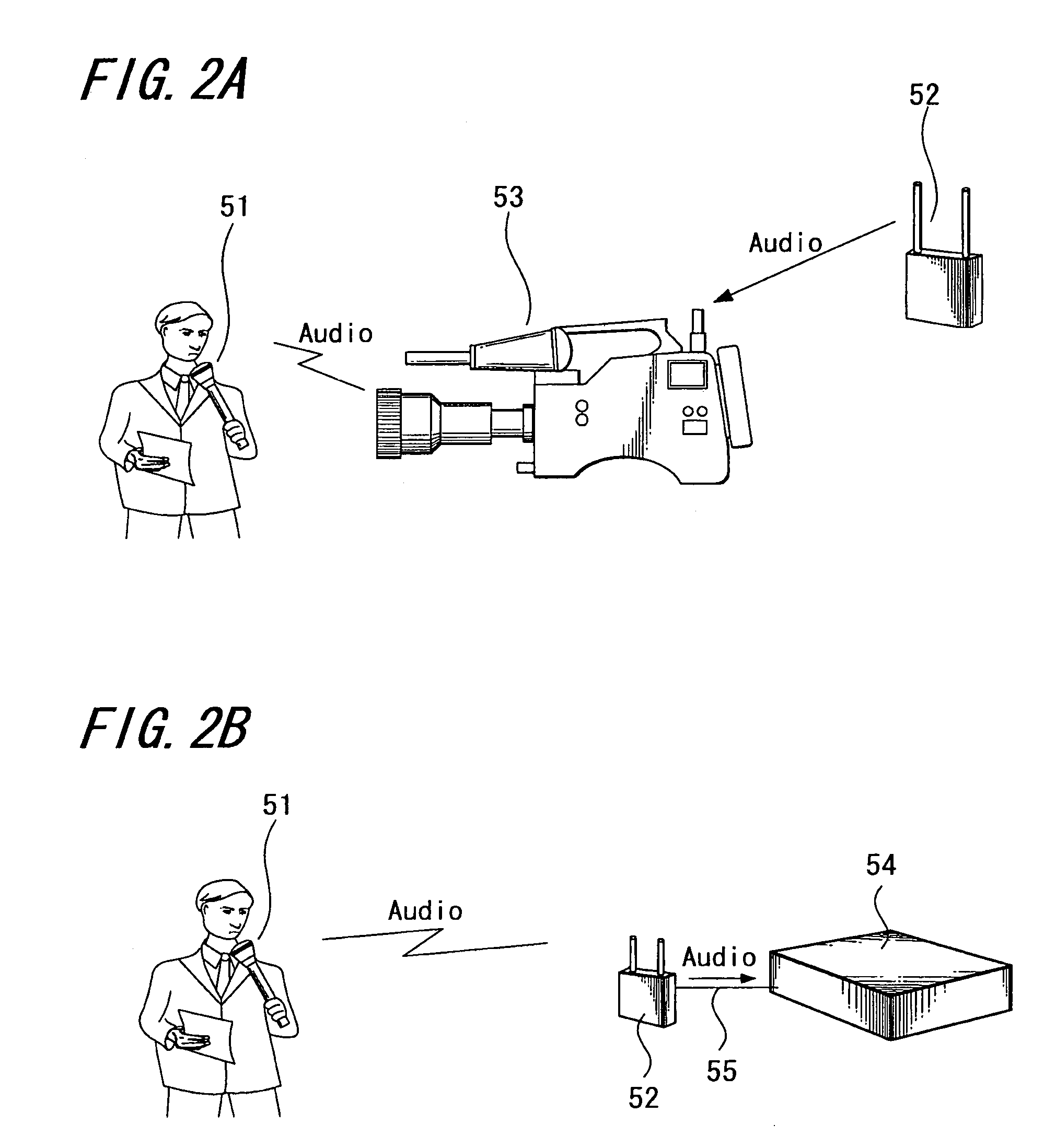
However, when the receiver 52 is attached or connected to the video camera 53 as shown in FIG. 2A, there is recognized such a disadvantage that operability may be reduced if a camera operator views the display of the receiver 52 while recording video with a video camera particularly after starting the news coverage.
Further, when the receiver 52 is connected to the audio mixer 54 as shown in FIG. 2B, there is also recognized such a disadvantage that operability may be reduced if an operator views the display of the receiver 52 while operating the audio mixer 54 after starting the news coverage.

Method used


Image

  • Wireless audio transmission system, receiver, video camera and audio mixer
  • Wireless audio transmission system, receiver, video camera and audio mixer
  • Wireless audio transmission system, receiver, video camera and audio mixer

Examples


Embodiment Construction

[0040]Hereinafter, embodiments of the present invention are specifically explained using the accompanied drawings. In the followings, two systems are explained, one of which is a system where an audio signal is input from a wireless microphone into a VTR-incorporated video camera, and the other of which is a system where an audio signal is input from a wireless microphone into an audio mixer.

[System with Audio Signal Input Into Video Camera]

[0041]FIG. 3 shows an embodiment of an audio transmission system to which the present invention is applied. Similarly to the system shown in FIG. 2A, audio transmitted using a wireless microphone is input into a VTR-incorporated video camera at the site of news coverage or the like.

[0042]A wireless microphone transmitter receiver (hereinafter, referred to as a receiver) 1 is attached to a receiver insertion slot that is provided in the rear of a VTR-incorporated video camera 2. A wireless microphone transmitter (hereinafter, referred to as a tran...


PUM


Abstract

A wireless audio transmission system includes: a transmitter having a microphone and a modulator-transmitter transmitting a radio wave modulated by an audio signal from the microphone; a receiver having a receiver-demodulator demodulating the audio signal after receiving the radio wave transmitted from the transmitter, outputting the audio signal demodulated by the receiver-demodulator to the outside of the receiver; and a video camera into which the audio signal output from the receiver is input, wherein the receiver has a detector detecting frequencies of a radio wave not being used by other devices based on a reception level of the radio wave received by the receiver-demodulator and outputs available frequency information indicating the frequencies detected by the detector to the video camera, and the video camera has a controller causing the available frequency information input from the receiver to be displayed on a display unit attached to the video camera.

Description

CROSS REFERENCES TO RELATED APPLICATIONS[0001]The present invention contains subject matter related to Japanese Patent Application JP 2005-217821 filed in the Japanese Patent Office on Jul. 27, 2005, the entire contents of which being incorporated herein by reference.BACKGROUND OF THE INVENTION[0002]1. Field of the Invention[0003]The present invention relates to a system in which audio to be recorded is transmitted using a wireless microphone. Further, the present invention relates to a receiver, a video camera and an audio mixer that constitute the system.[0004]2. Description of the Related Art[0005]In recent years, recording audio that is transmitted using a wireless microphone has become popular when gathering news materials and the like. FIG. 1 is a diagram showing an example of an external appearance of a wireless microphone. A wireless microphone transmitter (hereinafter referred to as a transmitter) 51 basically has a microphone and a modulator-transmitter transmitting a radi...

Claims


Application Information

Patent Timeline
Patent Type & Authority Patents(United States)
IPC IPC(8): H04N7/18
CPCH04H20/04H04H20/63H04N5/222H04N5/28H04N5/60H04N5/772H04N9/802H04N23/633H04B1/40H04R3/00
Inventor YAHAGI, YOSHIYUKI
Owner SONY CORP
Learn More