Drying apparatus and printing apparatus

a printing apparatus and drying apparatus technology, applied in printing, other printing apparatus, etc., can solve the problems of insufficient heating of endless belts, constant temperature drop of endless belts, and difficulty in using apparatuses, so as to avoid insufficient or uneven drying and high speed

Active Publication Date: 2013-11-05
CANON KK
View PDF7 Cites 1 Cited by
  • Summary
  • Abstract
  • Description
  • Claims
  • Application Information

AI Technical Summary

Benefits of technology

[0010]According to the present invention, a drying apparatus suitable for a printing apparatus that is capable of high-speed continuous printing is provided. Since sheets can be dried reliably in high speed continuous printing, insufficient or uneven drying can be avoided.

Problems solved by technology

However, it is difficult to use the apparatus disclosed in Japanese Patent No. 2657571 for high speed continuous printing for the following reasons.
During the continuous printing, the hot air blowing on the endless belt is blocked by the sheets and thus heating of the endless belt becomes insufficient.
As a result, the temperature of the endless belt decreases continuously as the printing is continued for a long time, and when the temperature is below the lower limit permissive temperature for obtaining necessary drying performance (T-min), drying performance which is necessary cannot be exhibited.
However, due to the upper limit permissive temperature of resistance to heat of the sheet (T-max), the temperature of the hot air cannot be increased excessively.
The T-max of the sheet is, for example, 90 degrees C. and it is undesirable to heat the sheet to a temperature above the T-max.

Method used


Image

  • Drying apparatus and printing apparatus
  • Drying apparatus and printing apparatus
  • Drying apparatus and printing apparatus

Examples


first embodiment

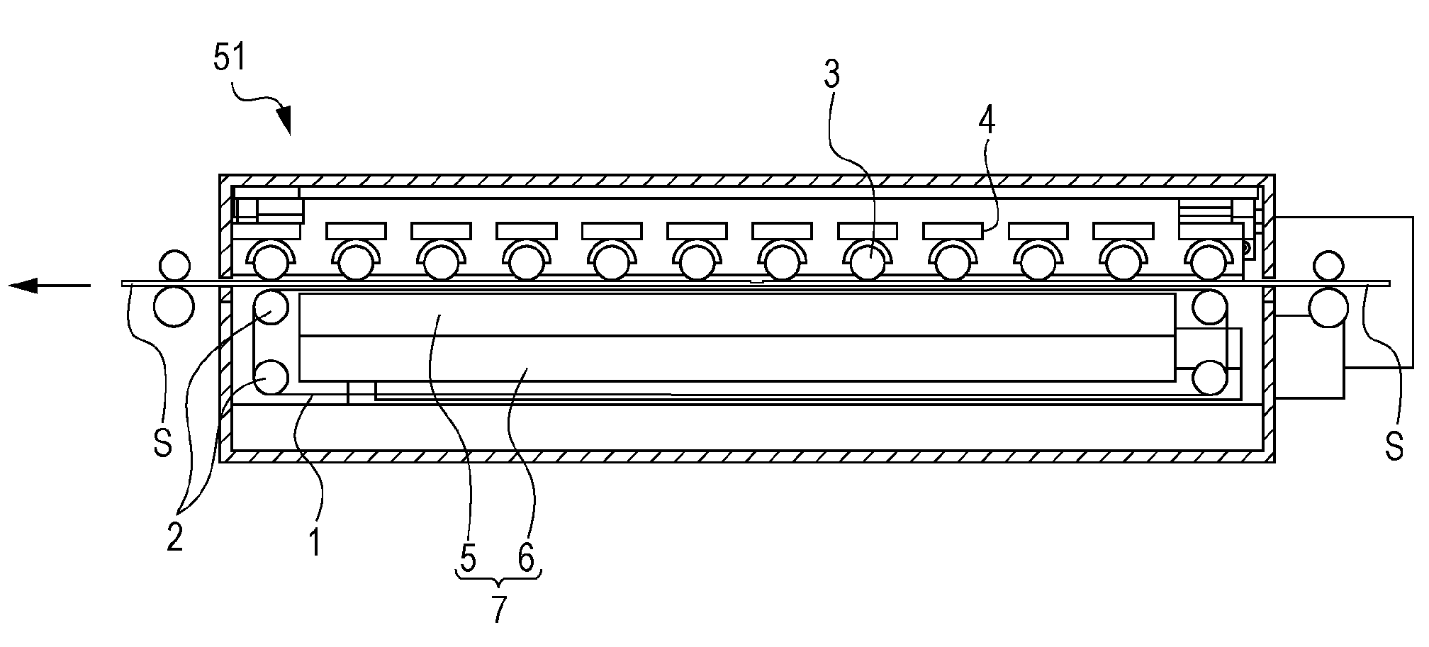
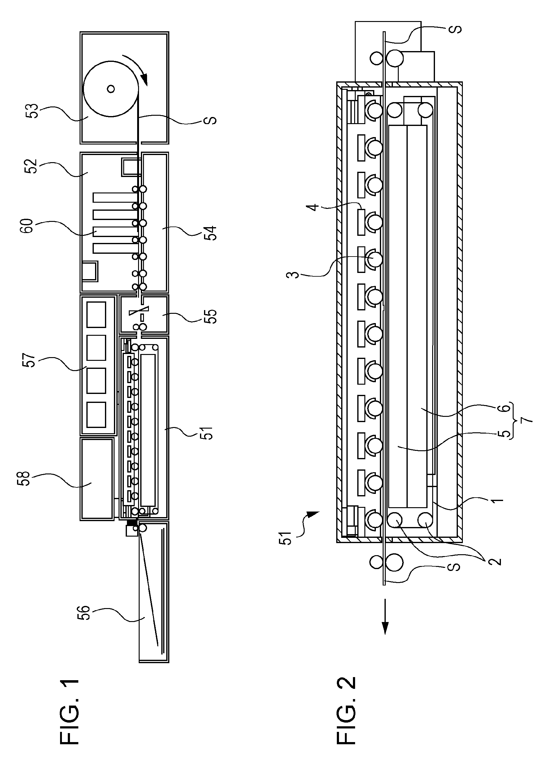
[0024]FIG. 1 is an overall structural view of an inkjet printing apparatus according to the present embodiment. The printing apparatus includes therein a sheet feeding unit 53, a printing unit 52, a cutting unit 55, a drying unit 51, a sheet discharge unit 56, an ink tank unit 57 and a control unit 58. A sheet S is conveyed, by a conveyance mechanism consisting of pairs of rollers and a belt, along a sheet conveyance path which is directed from the right to the left as illustrated in FIG. 2 and is processed in each of the units.

[0025]The sheet feeding unit 53 accommodates a rolled-up continuous sheet and supplies the same. The sheet feeding unit 53 can accommodate one or more rolls, and the sheet S is drawn and supplied from any desired one of the rolls.

[0026]The printing unit 52 forms an image on the sheet by applying ink from print heads 60 on the sheet which is being conveyed. The printing unit 52 also includes a plurality of conveying rollers which convey the sheet. Each of the ...

second embodiment

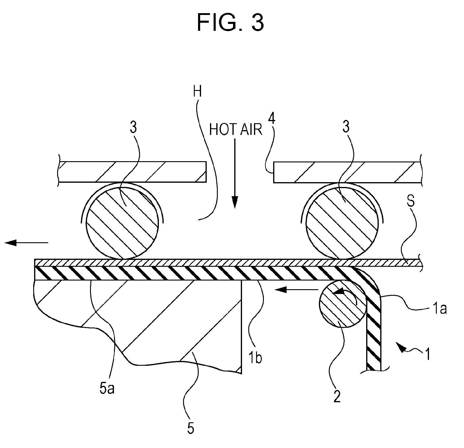
[0048]Next, a second embodiment will be described. In high density printing, i.e., high-duty printing with a large amount of ink applied per unit area, it is possible that marks of divided small roller sections of rollers 3 as illustrated in FIG. 4 might appear on a surface of a sheet S. The reasons for this phenomenon are considered to be as follows: the sheet S having been subject to high density printing has a high moisture content and thus easily softens and deforms; and the sheet S is easily deformed due to stress concentration at boundaries of ends of the small roller sections and gaps Δd.

[0049]In the second embodiment, urging force for each of the small roller sections is determined independently such that each of the small roller sections apply the urging force suitable for reliable high speed conveyance of the sheet S without any severe deformation on the sheet surface. FIG. 10 is a sectional view of a structure of a main part of an apparatus according to the second embodim...


PUM


Abstract

A drying apparatus includes: a rotatable belt which has an outer surface and an inner surface, the outer surface contacts a sheet; a blowing mechanism which blows hot air on the sheet at a side of the outer surface; and a heating unit which includes a heating element and a contact surface which is disposed in contact with the inner surface. A plurality of rollers are arranged in a direction in which the sheet travels. The rollers are pressed against the outer surface of the belt with the travelling sheet being held between the rollers and the outer surface of the belt.

Description

BACKGROUND OF THE INVENTION[0001]1. Field of the Invention[0002]The present invention relates to a drying apparatus which dries sheets with high moisture content after printing, and a printing apparatus.[0003]2. Description of the Related Art[0004]In a printing apparatus, a sheet should be dried after becoming wet in an image formation process. The sheet may be dried naturally or in a forced manner for short time drying. Japanese Patent No. 2657571 discloses an apparatus in which a photosensitive sheet of a silver halide photosensitive material is subject to forced drying after becoming wet in a developing process. The disclosed apparatus includes an endless belt provided along a sheet travelling direction. The endless belt rotates in contact with a back surface of the sheet. Hot air is blown on the endless belt through an ejection port to increase a temperature of the belt. This means that the endless belt is heated by the hot air. The heated belt contacts the sheet which is being ...

Claims


Application Information

Patent Timeline
Patent Type & Authority Patents(United States)
IPC IPC(8): B41J2/01
CPCB41J29/377B41J11/002B41J11/0022B41J11/0024
Inventor SAITO, RIICHIKOITABASHI, NORIBUMIKANKE, TSUYOSHIMURO, KENTAROUOKUBO, AKIOSUZUKI, YOSHIAKI
Owner CANON KK
Why Eureka
Try Eureka