Position adjusting device for steering wheel

a technology of adjusting device and steering wheel, which is applied in the direction of steering column, steering parts, vehicle components, etc., can solve the problems of increasing operational burden, increasing the cost of this position adjusting device for steering wheel, and affecting the assembly operation, so as to achieve high level of efficiency in assembly operation, increase the force of maintaining position, and effectively prevent inadvertent displacement of the steering wheel position

Active Publication Date: 2013-11-12
NSK LTD
View PDF24 Cites 18 Cited by
  • Summary
  • Abstract
  • Description
  • Claims
  • Application Information

AI Technical Summary

Benefits of technology

[0034]In the case of the position adjusting device for a steering wheel according to the present invention configured as described above, the first and second friction members are arranged on the inside of the supporting plate section that constitutes the fixed side bracket, and these respective friction members therefore become covered by this supporting plate section. As a result, it is possible to prevent interference of the respectively thin-plate-shaped first and second friction members, with other members existing therearound or the body of a driver.
[0035]Moreover, by increasing the number of the first and second friction members and furthermore the friction area between these respective friction members, and by increasing the force of maintaining the position of the steering wheel in a fixed state, it is possible to effectively prevent inadvertent displacement of the position of the steering wheel.
[0036]When implementing such a structure, if the left and right friction members are connected with a connecting section, then an operation of inserting the rod member through these through holes or elongated holes can be easily carried out, and a high level of efficiency in the assembly operation can be achieved.

Problems solved by technology

Moreover, still there is a possibility of injuries to the driver if part of the body of the driver such as the knee collides with an end edge of any one of the friction plates (24, 25) in the event of a collision accident or the like.
However, if the respective friction plates (24, 25) independently oscillate or turn, then such an alignment operation needs to be carried out for the respective friction plates (24, 25), increasing the operational burden.
As a result, it becomes an obstacle to assembly operation efficiency of the position adjusting device for a steering wheel, making it more difficult to achieve a cost reduction in this position adjusting device for a steering wheel.
However in the case of such a structure disclosed in Patent Document 2, it is necessary to carry out a welding operation in a state where the spacers and the base end sections of the respective friction plates are appropriately superposed, and therefore the operational burden in manufacturing is significant and a cost reduction cannot be easily achieved.Patent Document 1: Japanese Patent Application Publication No.

Method used


Image

  • Position adjusting device for steering wheel
  • Position adjusting device for steering wheel
  • Position adjusting device for steering wheel

Examples


Embodiment Construction

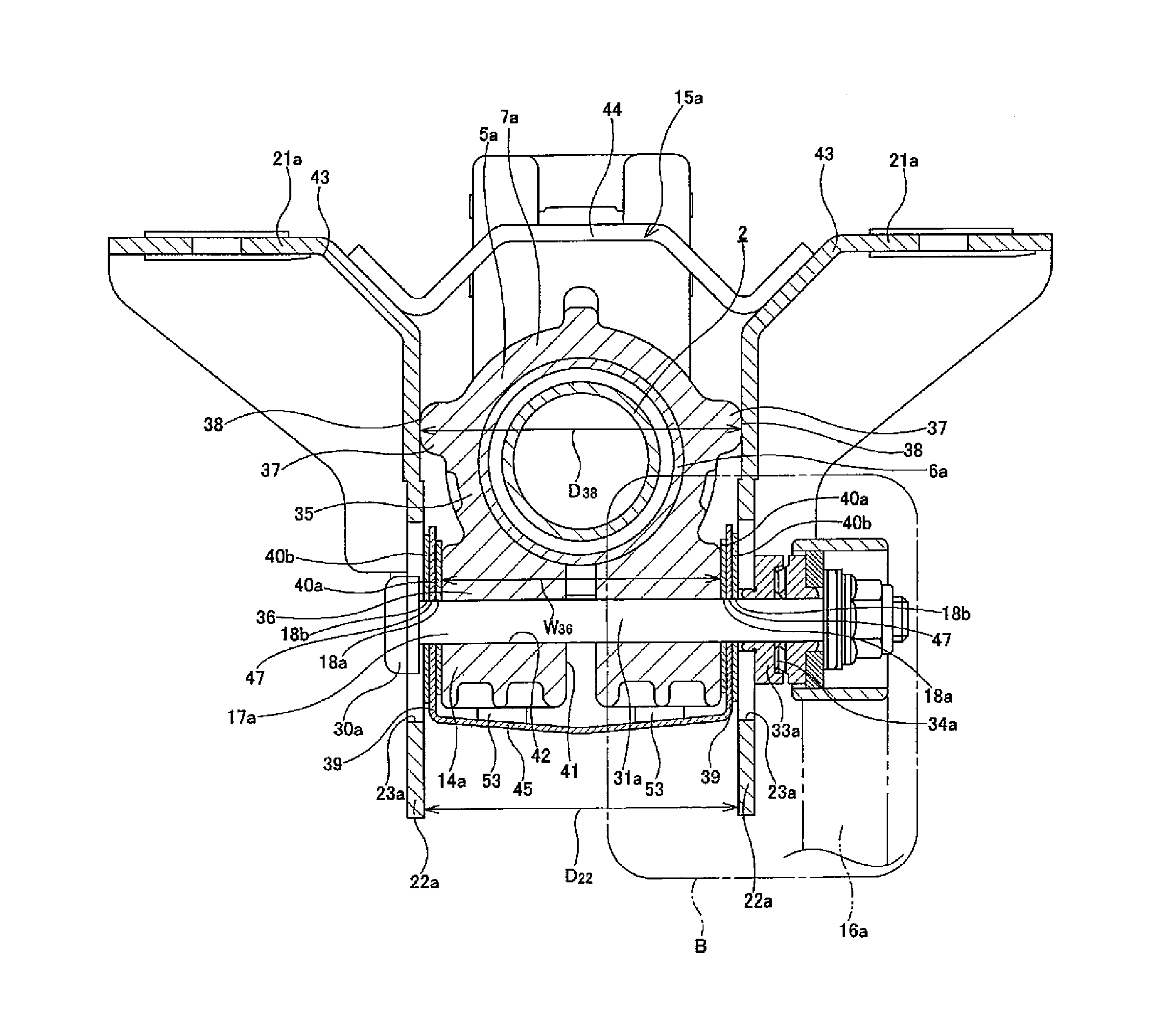
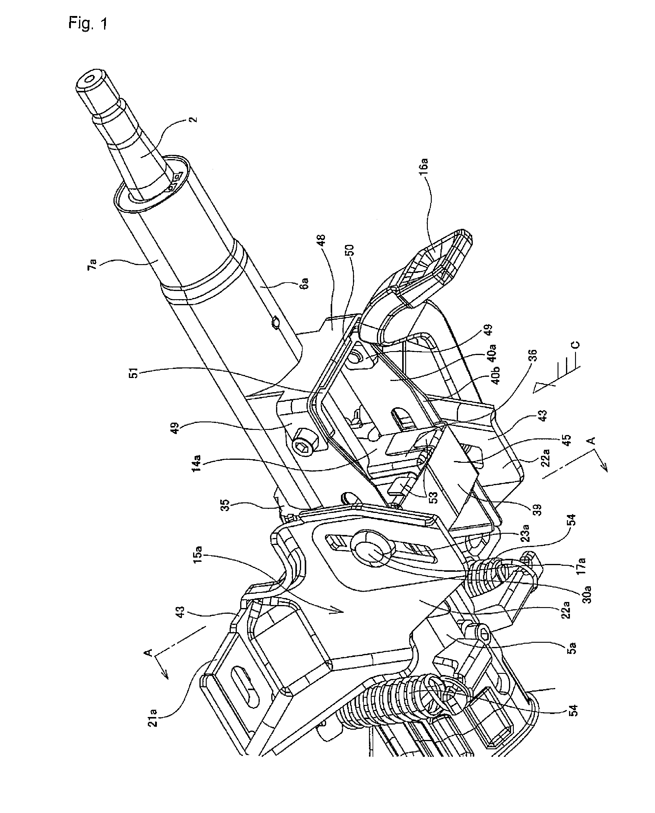
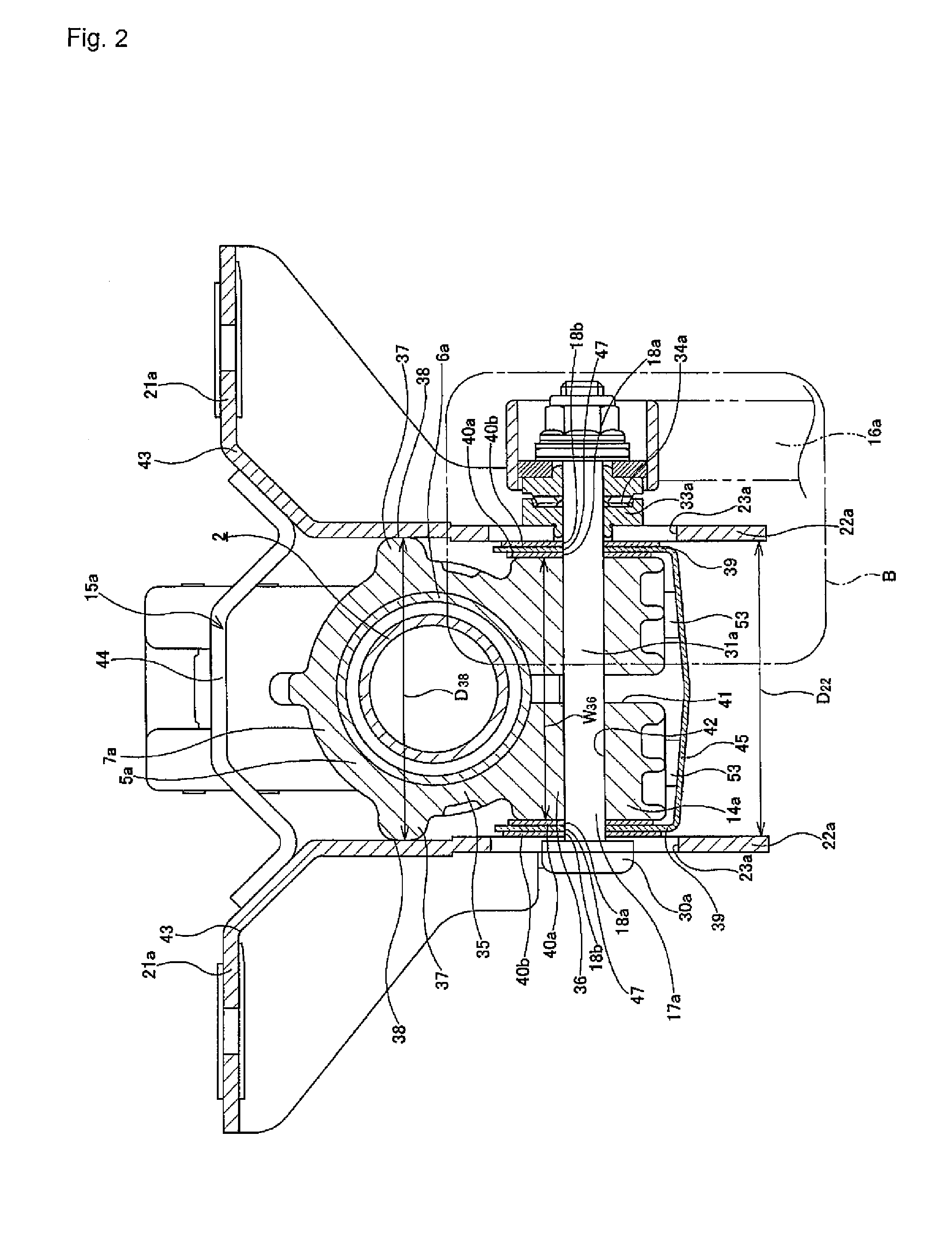
[0098]FIG. 1 to FIG. 5 show an example of an embodiment of the present invention. The front end section of a steering column (7a) that rotatably supports a steering shaft (2) inserted thereinside, is supported while being able to oscillate about a cross shaft (10) provided on an oscillating bracket (11) (refer to FIG. 6). With this configuration, it is possible, at the rear end section of the steering shaft (2), to adjust the height position of a steering wheel (1) (refer to FIG. 6) fixed on a portion protruding towards the rear side of the steering column (7a). Moreover, the steering shaft (2) and the steering column (7a), as with the conventional structure shown in FIG. 6, are capable of extension and retraction. With this configuration, it is possible to adjust the longitudinal position of the steering wheel (1).

[0099]In order to hold the vertical position and longitudinal position of this steering wheel (1) in a post adjustment position, a displacement side bracket (14a) is set ...


PUM


Abstract

A structure is realized that is capable of preventing interference of respective friction plates (39, 40a, 40b) with other members existing therearound or with the body of a driver, and furthermore that facilitates, when assembling, insertion of a tension rod (17a) through a circular hole (47) and longitudinal elongated holes (18a, 18b) formed in the respective friction plates (39, 40a, 40b). The respective friction plates (39, 40a, 40b) are arranged between both of the side faces of a displacement bracket section (36) and the inner face of supporting plate sections (22a) that constitute a fixed side bracket (15a). Moreover, the end edges of the respective friction plates (39, 40a, 40b) symmetrically present in pairs are connected by connecting sections (45, 46a, 46b), to thereby integrate the left and right friction plates (39, 40a, 40b) so that the respective holes (45, 18a, 18b), through which the tension rod (17a) is to be inserted, can be easily aligned.

Description

TECHNICAL FIELD[0001]The present invention relates to an improvement in a position adjusting device for a steering wheel that enables adjustment of the height position and longitudinal position of a steering wheel for steering a vehicle.BACKGROUND ART[0002]Heretofore, a position adjusting device for a steering wheel has been used for changing the height position or longitudinal position of a steering wheel according to the physical attribute of the body of a driver, the driving posture of the driver, and the like. In general, as such a position adjusting device, there has been used a structure in which a frictional force between a fixed side bracket supported and fixed on the vehicle body side and a displacement side bracket set on the steering column side is adjusted. That is to say, when adjusting the position of the steering wheel, an adjusting lever is operated in a predetermined direction to thereby reduce the frictional force acting between both of the above brackets. On the o...

Claims


Application Information

Patent Timeline
Patent Type & Authority Patents(United States)
IPC IPC(8): B62D1/16
CPCB62D1/184
Inventor MINAMIGATA, TAKAHIRO
Owner NSK LTD
Why Eureka
Try Eureka