Image display system

a display system and image technology, applied in static indicating devices, applications, instruments, etc., can solve the problems of time-consuming and laborious interpretation, insufficient comparison of data, and inability to accurately compare data, so as to save time, suppress the region of interest, and save time

Active Publication Date: 2013-11-12
FUJIFILM CORP
View PDF17 Cites 4 Cited by
  • Summary
  • Abstract
  • Description
  • Claims
  • Application Information

AI Technical Summary

Benefits of technology

[0011]The present invention is made in consideration of the above circumstances, and provides an image display system with which efficient interpretation can be made, and can suppress loci of attention from being overlooked.
[0013]According to the image display system of the first aspect of the present invention, the combination of images having the minimum number of images having all of the loci of attention expressed by the detected regions of attention in the specific number of images is selected from the combinations of the images by the selection section for display as images on the display section. Accordingly, since the minimum number of images are displayed in order to display all of the loci of attention, efficient interpretation can be made, while suppressing loci of attention from being overlooked.
[0016]According to the image display system of the third aspect of the present invention, cases where there are plural sets of image pairs determined, each image pair being a single set of two images, the selection section selects, from combinations of the image pairs, the combination of images for display as images on a display section, the combination of image pairs having the minimum number of the image pairs having all of the loci of attention expressed by the regions of attention detected in the specific number of images. Accordingly, since the minimum number of images are displayed in order to display all of the loci of attention, efficient interpretation can be made, while suppressing loci of attention from being overlooked.
[0019]According to the image display system of the fifth aspect of the present invention, time is saved when considering the three dimensional image of the breast N as a whole, and even more efficient interpretation can be made, while suppressing regions of interest being overlooked.

Problems solved by technology

However, the display of slice images only provides fragmentary data, and for a 3-dimensional image, consideration needs to be given to a combination made from the slice images, with the possibility of this leading to a tumor being overlooked.
It is also necessary to check all of the plural slice images, with the possibility that this leads to the time for interpretation being longer than previously.
In a 3-dimensional system, there is an advantage as a tool by which the breast can be envisaged all at once, however, since the data amount for displaying the breast as a whole is based on data from two images taken from a limited angular field of view of about 4 to 10 degrees, the amount of data is not sufficient in comparison to the amount of data obtained from the great number of images acquired by tomosynthesis imaging, and in particular it is not sufficient to find tumors and the like in dense breasts.

Method used


Image

  • Image display system
  • Image display system
  • Image display system

Examples


first exemplary embodiment

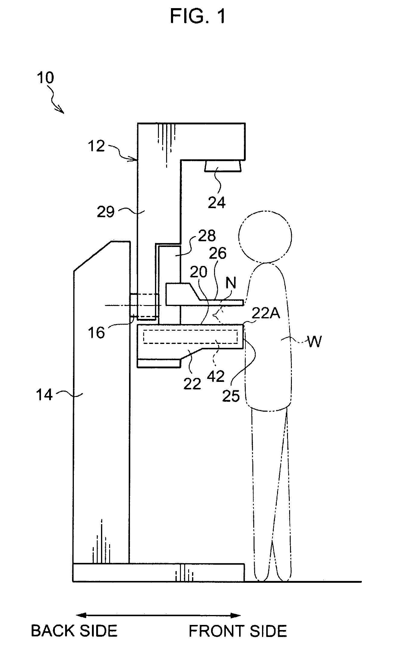
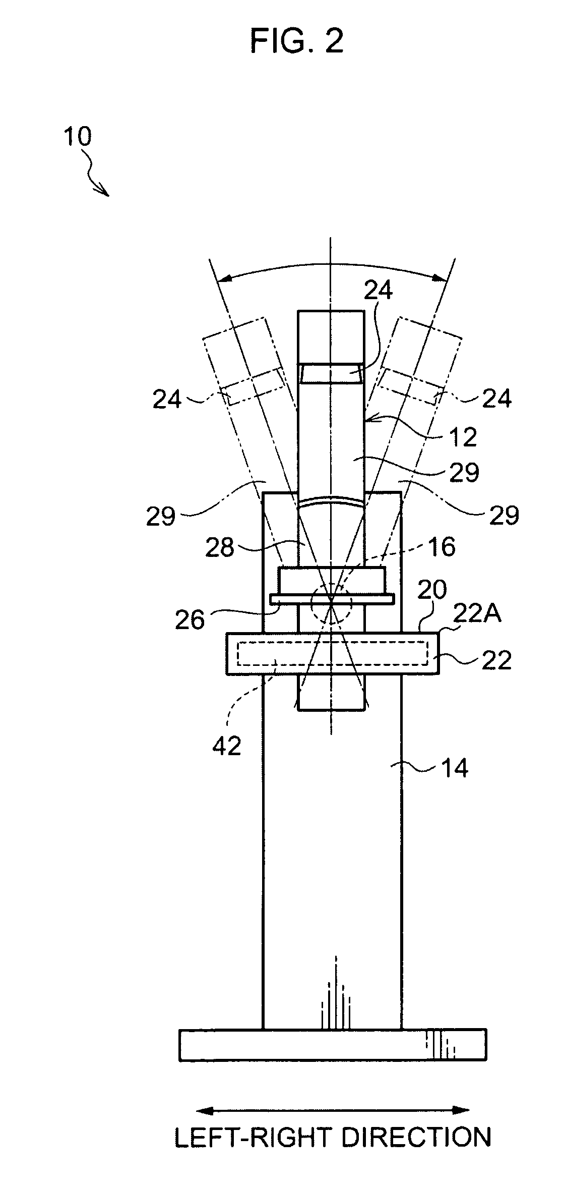
[0039]Explanation first follows regarding a first exemplary embodiment. As shown in FIG. 1 to FIG. 2, a radiographic imaging device 10 according to the present exemplary embodiment is a device for imaging a breast N of an investigation subject W using radiation (for example, X-rays) while the investigation subject W is in an upright state, referred to, for example, as mammography. In the explanation that follows, the near side in the vicinity of the investigation subject W when the investigation subject W faces the radiographic imaging device 10 during imaging is referred to as the device front side of the radiographic imaging device 10, the far side away from the investigation subject W when the investigation subject W faces the radiographic imaging device 10 is referred to as the device back side of the radiographic imaging device 10, and the left-right direction of the investigation subject W when the investigation subject W faces the radiographic imaging device 10 is referred to...

second exemplary embodiment

[0089]Explanation now follows regarding a second exemplary embodiment. Similar configuration and processing to that of the first exemplary embodiment is allocated the same reference numerals and further explanation thereof is omitted. The display device 80 is employed as the display section in the first exemplary embodiment, however, in the radiographic image display system 5′ of the present exemplary embodiment, as shown in FIG. 11, a stereoscopic display device 82 is employed as the display section. In the first exemplary embodiment, the CPU 60 of the image processing device 50 receives specific instructions and executes the first display control processing, however in the present exemplary embodiment, the CPU 60 receives specific instructions and executes second display control processing.

[0090]FIG. 12 shows an example of a configuration of the stereoscopic display device 82 according to the present exemplary embodiment.

[0091]As shown in FIG. 12, the stereoscopic display device 8...


PUM


Abstract

An image display system including: an image acquisition section that acquires a specific number of images of an imaging subject by imaging with an imaging section from different respective imaging positions; a detection section that detects regions of attention expressing specific loci of attention in each of the specific number of images acquired by the image acquisition section; and a selection section that selects, from combinations of the images, a combination of images for display as images on a display section, the combination of images having a minimum number of images having all of the loci of attention expressed by the regions of attention detected by the detection section in the specific number of images.

Description

CROSS-REFERENCE TO RELATED APPLICATION[0001]This application claims priority under 35 USC 119 from Japanese Patent Application No. 2010-079516, filed on Mar. 30, 2010, the disclosure of which is incorporated by reference herein.BACKGROUND[0002]1. Technical Field[0003]The present invention relates to an image display system.[0004]2. Related Art[0005]There are previously known radiographic imaging devices (imaging devices) that perform radiographic imaging for the purpose of medical diagnostics. For such types of radiographic imaging device, there is, for example, a known technique for performing tomosynthesis imaging to image a breast of an investigation subject from plural angles, for purposes such as early diagnosis of breast cancer.[0006]The slice images acquired of the breast by tomosynthesis imaging with images acquired from plural angles are particularly effective for highly dense (with many mammary glands) breasts (known as dense breasts). An example of the reason for this is ...

Claims


Application Information

Patent Timeline
Patent Type & Authority Patents(United States)
IPC IPC(8): G09G5/00G06K9/32G06K9/00
CPCA61B6/025A61B6/0414A61B6/462A61B6/466A61B6/502A61B6/5217G06T19/00G06T2210/41G16H50/30
Inventor KASHIWAGI, NOBUHIKOMURAMOTO, AYAKO
Owner FUJIFILM CORP
Why Eureka
Try Eureka