
Re-stabilized impact strut

a technology of impact struts and stabilizers, which is applied in the direction of shock absorbers, springs/dampers, elastic dampers, etc., can solve the problems of unyielding static stiffness of structures, and achieve the effect of higher compressive capacities

Inactive Publication Date: 2013-11-19
BETTINGER DAVID S +1
View PDF6 Cites 1 Cited by
  • Summary
  • Abstract
  • Description
  • Claims
  • Application Information

AI Technical Summary

Benefits of technology

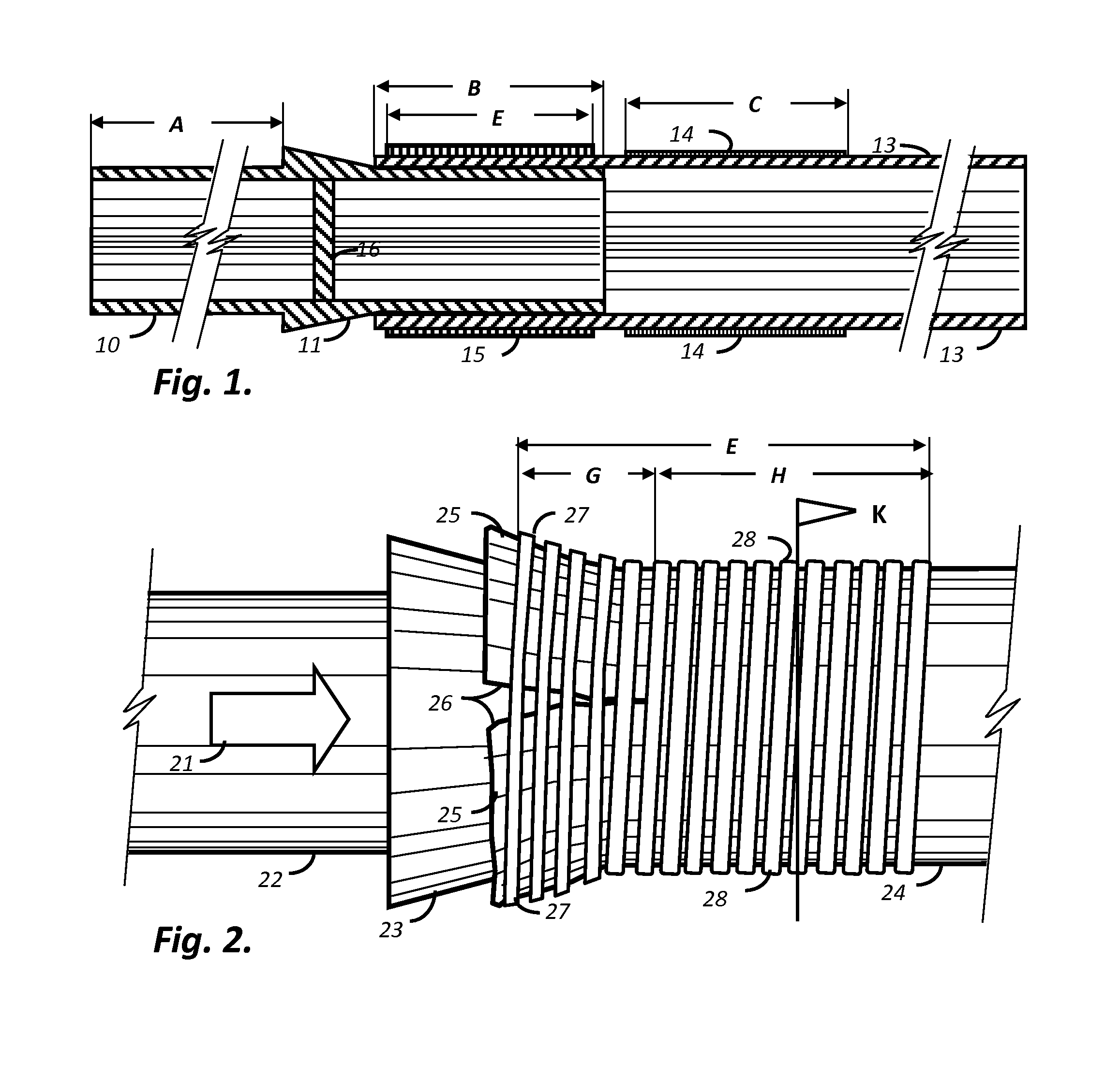
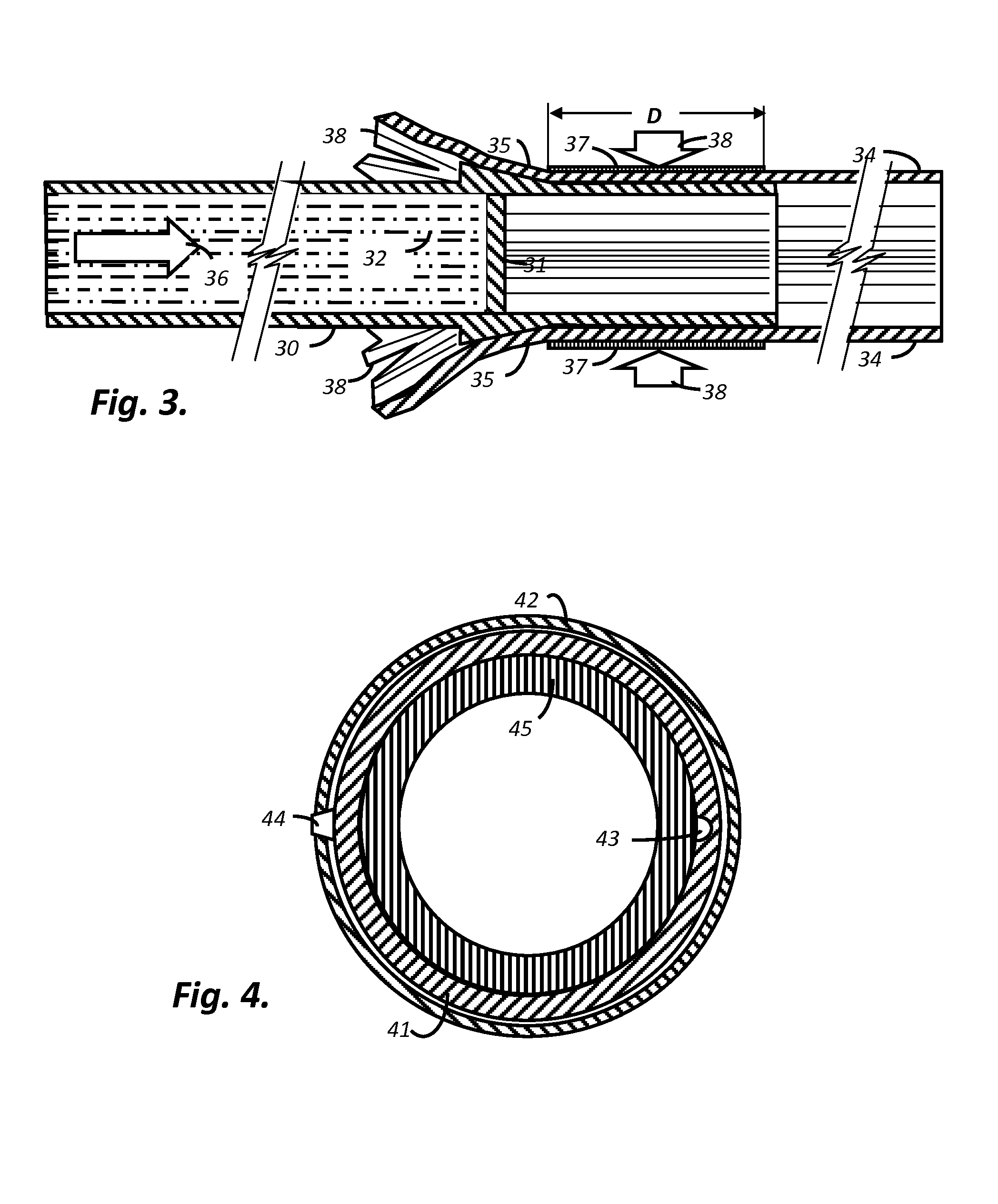
[0019]This current invention teaches that the impact member or expander addresses and attacks each ICCWB in sequence stretching these fibers to a predetermined strain by conical wedge action which may or may not be above their breaking point. This current invention teaches that the UCCWB may be fixed at some point for each wrap to assure that one band breakage doesn't unravel subsequent windings. For composites a continuous independent circumferential fiber winding may be fixed at one circumferential point on the wrap to prevent unwinding by previous fiber stretch and breakage.
[0021]A feature of the current invention is the sequential addressing of fiber bands until impact momentum is slowed and stopped to the limit of the strut capability, thereby translational damage is balanced and shorting of the strut is limited. The effect is that displacement of the semi-collapsed telescoping strut is limited to the amount of retardance necessary to absorb all of the impact energy by elastic strain. The result is that those at risk from catastrophic systemic failure due to a single component will be provided options for egress.
[0025]Stresses due to impact loads may be found using energy equations as long as materials operate within their elastic ranges. Elastic equations and elastic material behavior are most predictable for relatively heavy impacting masses moving at low velocities on impact. It is objective of the current invention to locate the joint far enough from the point of structural impact communication that despite some inelastic impact behaviors in the active impactor member the elongation of the bands generally operates within elastic ranges. This objective is an indicator that the active impactor member may be fabricated from metals and other non-composites with higher compressive capacities that insulate the bands from a higher-velocity impact pulse that would cause inelastic behavior material in the bands.
[0027]In a preferred embodiment of the current invention a bonded contact overlap of an inner and outer member, the inner member possessing an outwardly projecting conical taper adjacent to and external to the contact overlap, whereby a forced compressive axial movement of the inner member in relation to the outer member causes progressive sequential elastic strain of the generally circumferential fiber wound fibers as the axial displacement continues due to the wedge effect of increasing differential diameter of the active member, and whereby stable structural rigidity of the joint results after the forced compressive axial movement due to progressive new contact overlap of an inner and outer member in new congruent self-locking contact areas.

Problems solved by technology

But structures are designed for unyielding static stiffness.

Method used


Image

  • Re-stabilized impact strut
  • Re-stabilized impact strut
  • Re-stabilized impact strut

Examples


Embodiment Construction

[0027]In a preferred embodiment of the current invention a bonded contact overlap of an inner and outer member, the inner member possessing an outwardly projecting conical taper adjacent to and external to the contact overlap, whereby a forced compressive axial movement of the inner member in relation to the outer member causes progressive sequential elastic strain of the generally circumferential fiber wound fibers as the axial displacement continues due to the wedge effect of increasing differential diameter of the active member, and whereby stable structural rigidity of the joint results after the forced compressive axial movement due to progressive new contact overlap of an inner and outer member in new congruent self-locking contact areas.

[0028]An objective of the application of the current invention is to facilitate the responsive and immediate movement, acceleration, and translation of the active impactor member to directed axial impact. Immediate responsive impactor movement...


PUM


Abstract

Low-velocity axial impact thrust on a bonded telescoping middle joint of a strut is retarded and impact energy is converted and absorbed by the elastic strain of unfettered circumferentially bands. In a preferred embodiment an impacted strut regains structural integrity after impact displacement and fracture by re-bonding.

Description

CROSS-REFERENCE TO RELATED APPLICATIONS[0001]Not Applicable.STATEMENT REGARDING FEDERALLY SPONSORED RESEARCH OR DEVELOPMENT[0002]Not Applicable.THE NAMES OF THE PARTIES TO A JOINT RESEARCH AGREEMENT[0003]Not Applicable.INCORPORATION-BY-REFERENCE OF MATERIAL SUBMITTED ON A COMPACT DISC[0004]Not Applicable.BACKGROUND OF THE INVENTION[0005]The invention is related to structural bonded joints that are frangible due to impact momentum that is moderated during displacement by elastic tension means and further related to structural members able to survive impact by energy absorption despite displacement to new secure telescoping structural bonded surfaces and are thus restabilized. And further related to structures of polymer matrix composites impacted by low-velocity, non-ballistic impacts communicated by structural, hydraulic or pneumatic means.[0006]The invention is also directed to pipe sections constructed and their structural connections, and more particularly to couplings between bo...

Claims


Application Information

Patent Timeline
Patent Type & Authority Patents(United States)
IPC IPC(8): F16F7/12
CPCF16F7/125
Inventor BETTINGER, DAVID S.WHITNEY, THOMAS J.
Owner BETTINGER DAVID S
Learn More