
Roof seam tape applicator

a technology of adhesive tape and applicator, which is applied in the direction of paper hanging, tobacco, instruments, etc., can solve the problems of difficulty in applying proper pressure to the tape across the full width of the tape, the operator's view of conventional equipment, and the lack of direct viewing of the application of the sheet material on the rooftop, etc., to achieve the effect of convenient manual rotation

Inactive Publication Date: 2010-10-28
FIRESTONE BUILDING PRODS
View PDF27 Cites 11 Cited by
  • Summary
  • Abstract
  • Description
  • Claims
  • Application Information

AI Technical Summary

Benefits of technology

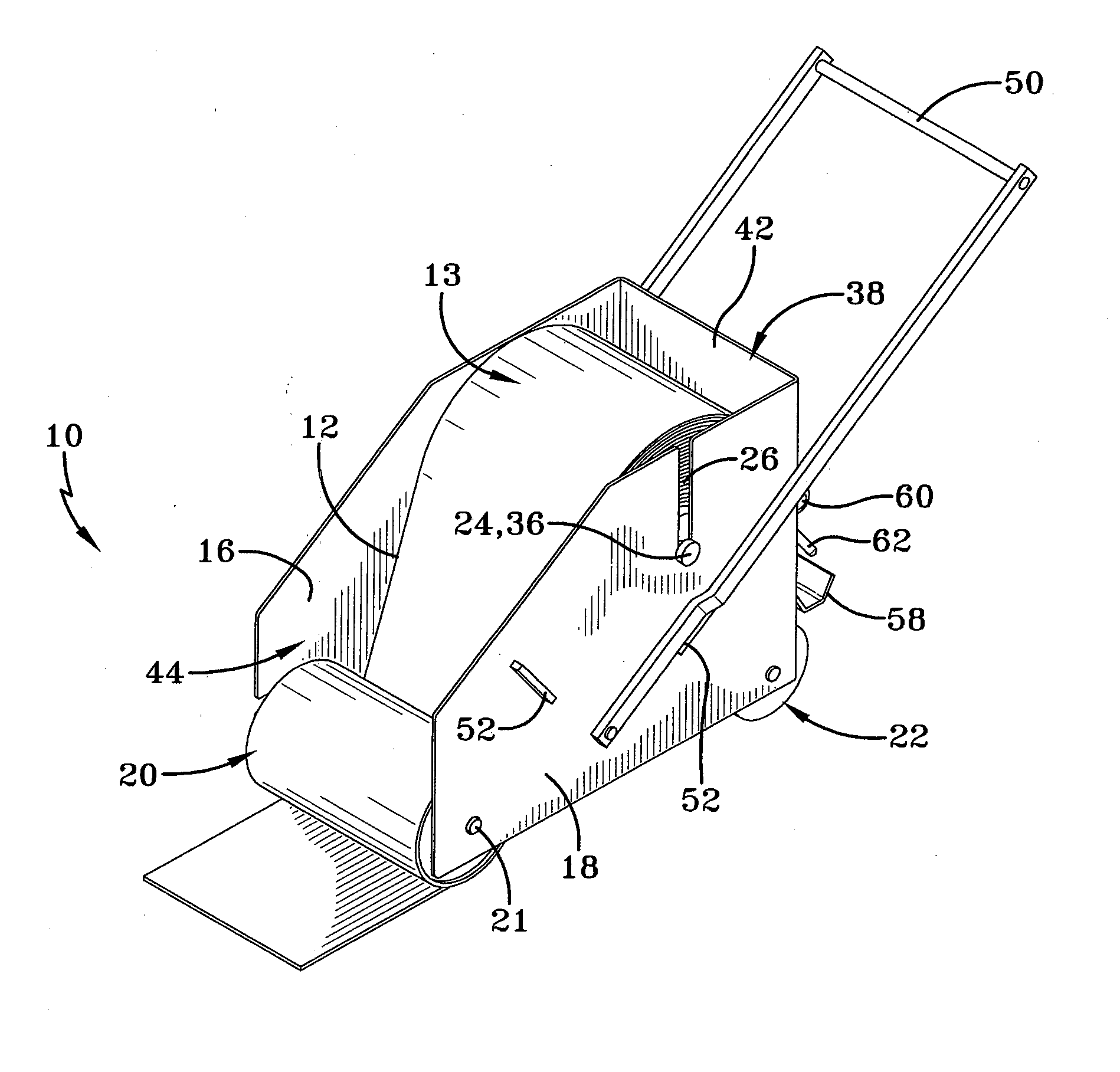
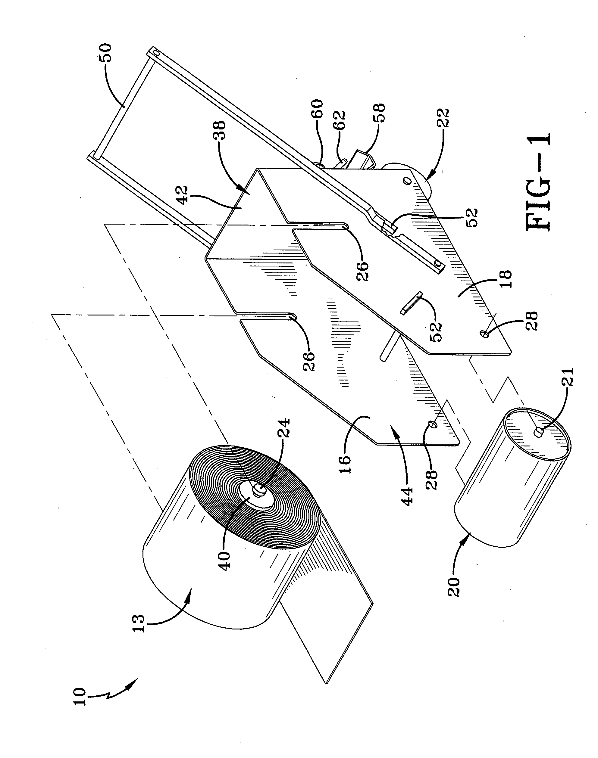
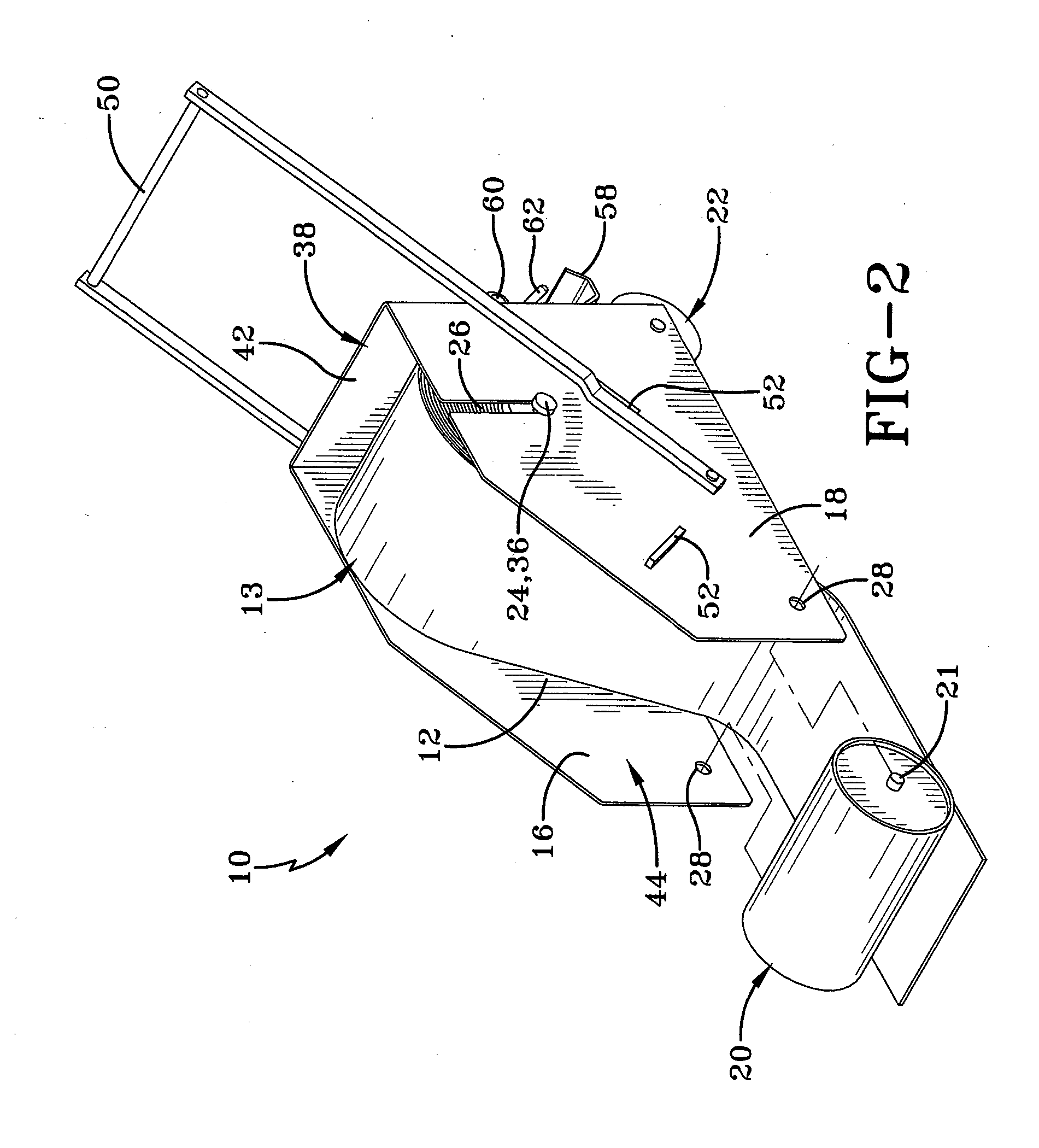
[0014]The pressure applicator may include a rotatable release liner take-up roll secured to the handle to collect the release liner of the adhesive tape as it is applied. The release liner take-up roll may include a crank arm to facilitate manual rotation thereof, or may be rotationally coupled to the support element or pressure applicator to cause automated rotation thereof while the device is pushed across a surface. A mechanism may also be provided to prevent unwinding of the release liner take-up roll.

Problems solved by technology

These prior art pieces of equipment have ranged from the effective but complicated to the ineffective.
Additionally, conventional applicators for sheet material on rooftops do not allow for direct viewing of the application of the sheet material to the roof.
In these conventional pieces of equipment, the elements of the equipment themselves block the view of an operator of the conventional equipment.
These other prior art attempts fail to provide a simple roofing seam tape applicator that facilitates easy alignment of the roofing tape onto the roof in the proper position and then allows the machine to be loaded with the roll of material for further application of the seam tape to the roof.
Additionally, the prior art attempts have had difficulty in applying proper pressure to the tape across the full width of the tape.
The inconsistencies may arise by improper balancing of the weight of the conventional applicators.
Additionally, the conventional applicators traditionally lack the ability to adjust to imperfections in the roofing surface.
This type of roofing seam tape applicator is lacking in the art.

Method used


Image

  • Roof seam tape applicator
  • Roof seam tape applicator
  • Roof seam tape applicator

Examples


Embodiment Construction

[0028]Referring generally now to FIGS. 1-7, a first embodiment of the apparatus of the current invention is shown and generally designated by the numeral 10. The apparatus (10) is for the placement of material (12) to a surface (14), while in a preferred embodiment the apparatus (10) may be used as a roofing seam tape applicator. The apparatus (10) comprises a first side (16), a second side (18), a removable pressure applicator (20), a support element (22), and a material axle (24).

[0029]In certain embodiments, the apparatus (10) may be utilized to apply an adhesive tape to a roofing membrane. The adhesive tape may be a solid adhesive, which may also be referred to as a solid adhesive strip, and may include those that are conventional in the art. In one or more embodiments, the adhesive tape may include EPDM and / or butyl rubber. In the same or other embodiments, the adhesive tape includes at least 85% solids. In one or more embodiments, the adhesive tape includes a thickness of grea...


PUM

PropertyMeasurementUnit
thicknessaaaaaaaaaa
thicknessaaaaaaaaaa
thicknessaaaaaaaaaa

Abstract

An apparatus for placement of seam tape to a roof or roof membrane. The apparatus comprises first and second sides spaced a distance apart, wherein each side includes a material axle opening and a pressure applicator orifice. The apparatus also comprises a removable pressure applicator having a first end and second end positioned in the pressure applicator orifices of the first and second sides. A support element may be operatively attached to the first and second sides, span the distance between the first and second sides, and positioned opposite the pressure applicator to support the apparatus. Additionally, a material axle may be positioned such that its ends are removably positioned in the material axle openings of the first and second sides. A closed front side may connect the first and second side, while an open stern may allow direct access to the pressure applicator, the support element, and the material axle.

Description

[0001]This application is a Continuation-in-Part of U.S. Non-provisional application Ser. No. 11 / 350,609 filed on Feb. 9, 2006, which claims the benefit of U.S. Provisional Application No. 60 / 742,546, filed Feb. 9, 2005, which Applications are incorporated herein by reference in their entirety.FIELD OF THE INVENTION[0002]The present invention relates generally to adhesive applicators. More particularly, the present invention relates to an apparatus for the placement of seam tape to a roof, a roofing membrane, or to a membrane used with a low-slope roof, the apparatus may be described as a roofing seam tape applicator.BACKGROUND OF THE INVENTION[0003]It will be appreciated by those skilled in the art that commercial equipment is available to apply roofing seam tape to a single ply membrane surface. Such conventional systems have been generally designed to lay material on a roof that comes in roll form and is applied in sheet form. These prior art pieces of equipment have ranged from ...

Claims


Application Information

Patent Timeline
Patent Type & Authority Applications(United States)
IPC IPC(8): E04D15/06
CPCY10T156/1795E04D15/04
Inventor KALWARA, JOSEPH JOHNHEATHCOTE, JOHNWARD, BRANDON JAYHENEGAR, JEFFREY W.
Owner FIRESTONE BUILDING PRODS
Learn More