Lumbar support device

a technology for supporting devices and lumbar spines, which is applied in the direction of folding chairs, dismountable chairs, stools, etc., can solve the problems of difficult to immobilize the device in a different seating unit, difficult production and relatively complicated and potentially costly, and muscle fatigue or muscle pain in the lower back region is very common, so as to reduce muscle fatigu

Active Publication Date: 2013-11-19
SRITHAI AUTOSEATS IND COMPANY
View PDF30 Cites 14 Cited by
  • Summary
  • Abstract
  • Description
  • Claims
  • Application Information

AI Technical Summary

Benefits of technology

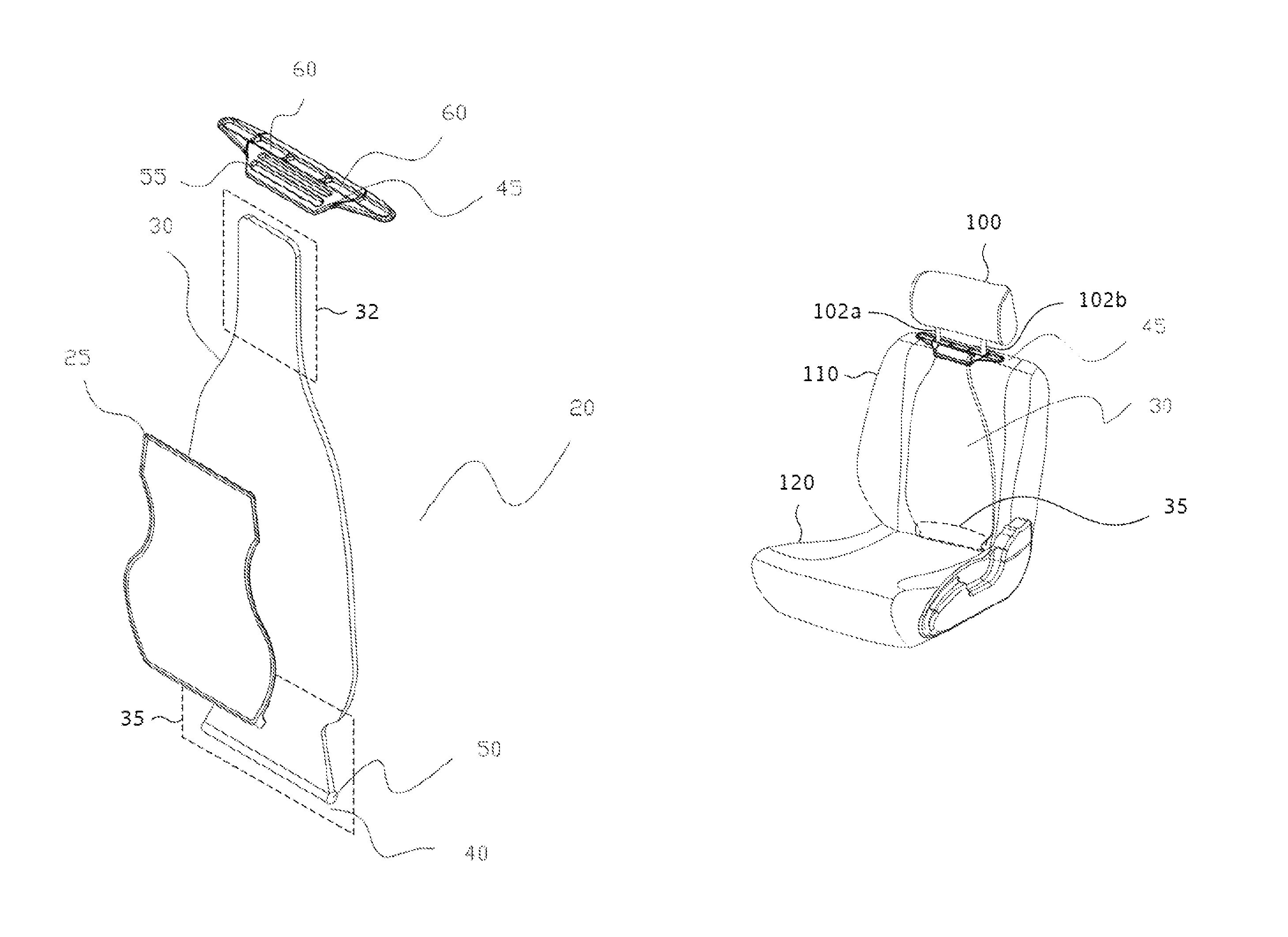
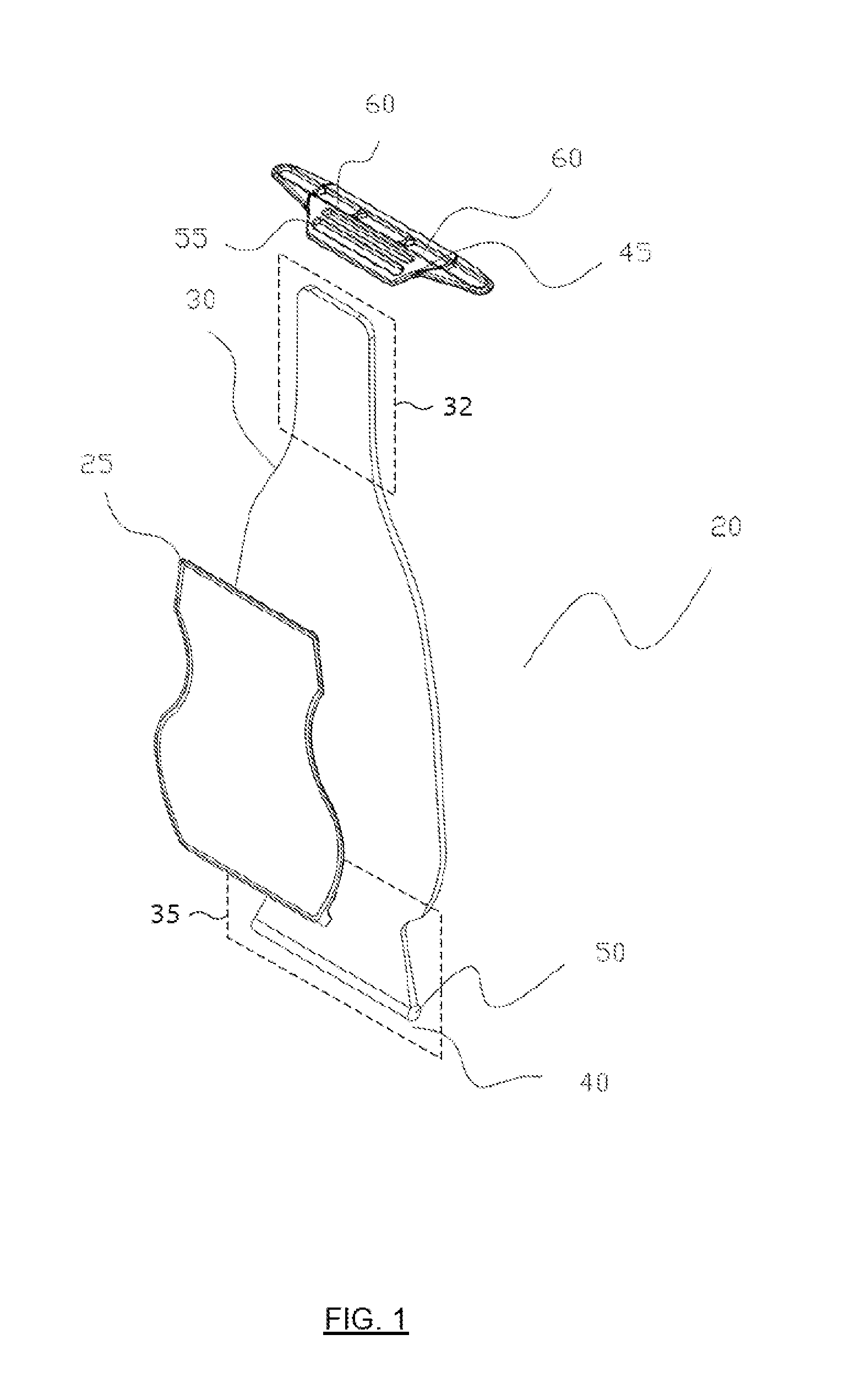
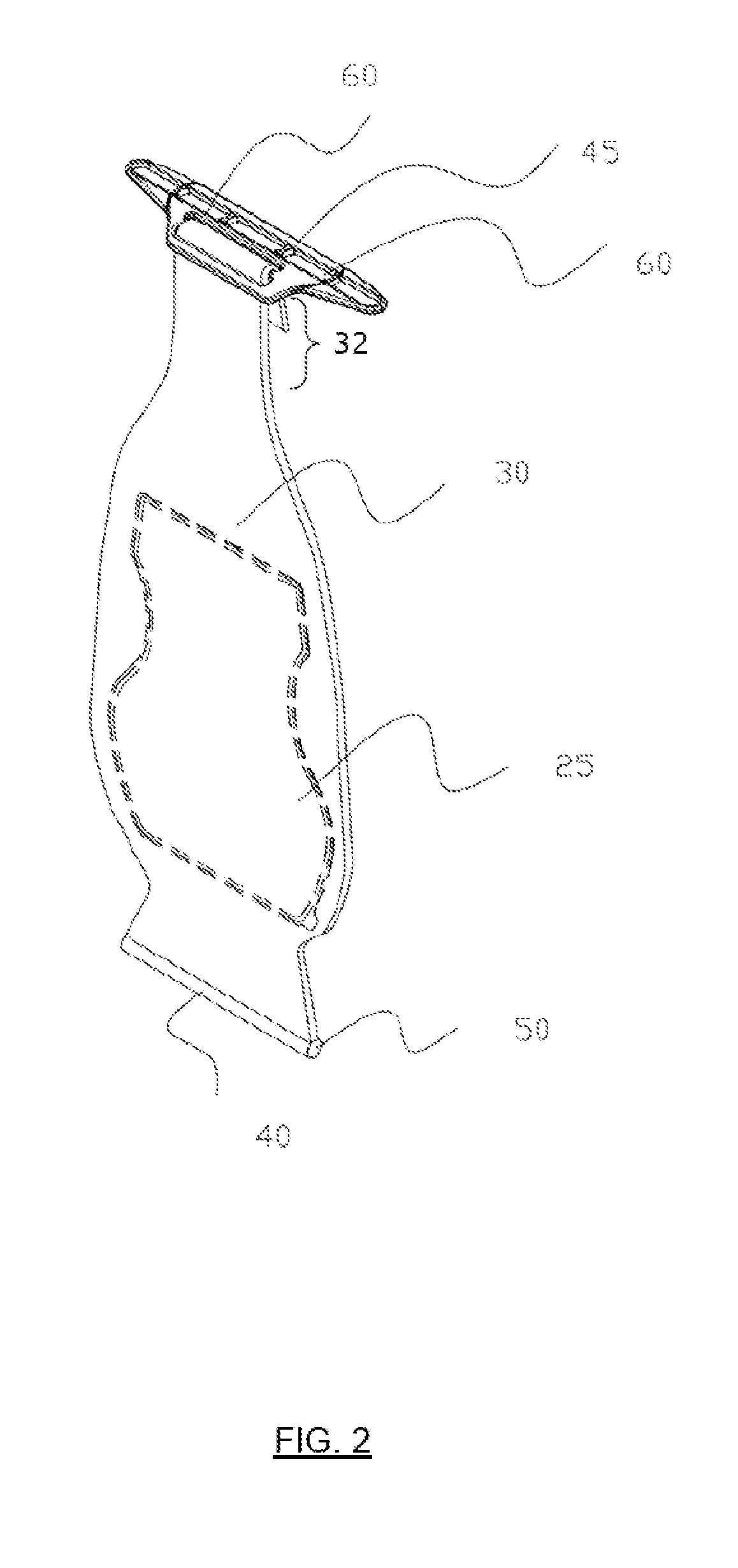
[0010]The invention disclosed herein concerns a back supporting device for use with seating apparatuses. The present back support device may comprise a bag, having a shape corresponding to the general shape of a person's back, the bag comprising at least one compartment holding a predetermined amount of fluid or gas; a flexible cover encasing the bag, and fastening elements for securing the device to the seating apparatus. The edge of the bag is sealed or stitched to the cover, thereby holding the bag in place. The fluid inside the compartment may move in multiple directions in response to the application of pressure or weight from a person leaning against or pressing upon the seating apparatus backrest. The device can be secured to a seating apparatus to secure the device in place using the fastening elements. When seated, the person's back (preferably, the lumbar region) presses against the device (preferably, the fluid or gas contained in the bag), causing the contents of the bag to move in multiple directions in response to pressure applied by the person or movement of the person, thereby providing support and at the same time inducing muscle movement or massaging the person's back, thereby reducing muscle fatigue, preferably in the lumbar region.

Problems solved by technology

After an extended period of sitting, muscle fatigue or muscle pain in the lower back region is very common.
The disadvantages of the aforementioned back support devices are that they tend to be relatively complicated in their components and structures, thus making production relatively complicated and potentially costly.
As a result, it is challenging to immobilize the device in a different seating unit.
In addition, the installation and maintenance of such back support devices may require professional help or may need to be pre-assembled from the seating apparatus production site.

Method used


Image

  • Lumbar support device
  • Lumbar support device
  • Lumbar support device

Examples


Embodiment Construction

[0025]Reference will now be made in detail to various embodiments of the invention, examples of which are illustrated in the accompanying drawings. While the invention will be described in conjunction with the following embodiments, it will be understood that the descriptions are not intended to limit the invention to these embodiments. On the contrary, the invention is intended to cover alternatives, modifications and equivalents that may be included within the spirit and scope of the invention as defined by the appended claims. Furthermore, in the following detailed description, numerous specific details are set forth in order to provide a thorough understanding of the present invention. However, it will be readily apparent to one skilled in the art that the present invention may be practiced without these specific details. In other instances, well-known methods, procedures, components, and circuits have not been described in detail so as not to unnecessarily obscure aspects of th...


PUM


Abstract

Disclosed is a back supporting device for use with seating apparatuses. The back support device includes a bag containing at least one compartment holding a predetermined amount of fluid, liquid or gel, a flexible cover encasing the bag, and fastening elements for securing the device to the seating apparatus. The device is secured to a seating apparatus to secure the device in place. The fluid, liquid or gel inside the compartment is able to move in response to an application of pressure. When seated, the person's back presses against the device, in particular, the fluid, liquid or gel in the bag, causing the substance inside the bag to move in multiple directions in response to the movement of the person, thereby providing support and at the same time inducing muscle movement and reducing muscle fatigue in the back of the person, in particular in the lumbar region.

Description

FIELD OF THE INVENTION[0001]The present invention relates to a back support device. More particularly, the invention relates to a device for use with a seating apparatus such as office chair, automotive vehicle seat, etc., to provide back support, in particularly, to the lumbar region for the user.DISCUSSION OF THE BACKGROUND[0002]After an extended period of sitting, muscle fatigue or muscle pain in the lower back region is very common. Many individuals resort to various kinds of back supports. One of the most common forms of a back support is a pillow filled with synthetic fibers, foam beads or avian plumage. Over time, improvements to back support apparatuses have been developed. For example:[0003]U.S. Pat. No. 4,467,484 discloses a pneumatic cushion fabricated from two sheets of expandable materials, welded together to define an expandable pneumatic chamber. The welded portion is separated from the pneumatic chamber by a rigid board. The board is positioned on one side of the pne...

Claims


Application Information

Patent Timeline
Patent Type & Authority Patents(United States)
IPC IPC(8): A47C7/42
CPCA47C7/425B60N2/66B60N2/6054
Inventor LIMPAITOON, TONGCHAI
Owner SRITHAI AUTOSEATS IND COMPANY
Why Eureka
Try Eureka