Wireless energy transfer using repeater resonators

a repeater resonator and wireless technology, applied in the direction of electric energy management, driver interaction, inductance, etc., can solve the problems of inconvenient electrical energy transfer, inconvenient use, and inefficient radiative transfer

Active Publication Date: 2013-11-19
WITRICITY CORP
View PDF558 Cites 210 Cited by
  • Summary
  • Abstract
  • Description
  • Claims
  • Application Information

AI Technical Summary

Benefits of technology

[0016]In the wireless energy transfer systems we describe, remote devices may be powered directly, using the wirelessly supplied power or energy, or the devices may be coupled to an energy storage unit such as a battery, a super-capacitor, an ultra-capacitor, or the like (or other kind of power drain), where the energy storage unit may be charged or re-charged wirelessly, and / or where the wireless power transfer mechanism is simply supplementary to the main power source of the device. The devices may be powered by hybrid battery / energy storage devices such as batteries with integrated storage capacitors and the like. Furthermore, novel battery and energy storage devices may be designed to take advantage of the operational improvements enabled by wireless power transmission systems.

Problems solved by technology

However, this type of radiative transfer is very inefficient because only a tiny portion of the supplied or radiated power, namely, that portion in the direction of, and overlapping with, the receiver is picked up.
Such inefficient power transfer may be acceptable for data transmission, but is not practical for transferring useful amounts of electrical energy for the purpose of doing work, such as for powering or charging electrical devices.
However, these directed radiation schemes may require an uninterruptible line-of-sight and potentially complicated tracking and steering mechanisms in the case of mobile transmitters and / or receivers.
In addition, such schemes may pose hazards to objects or people that cross or intersect the beam when modest to high amounts of power are being transmitted.

Method used


Image

  • Wireless energy transfer using repeater resonators
  • Wireless energy transfer using repeater resonators
  • Wireless energy transfer using repeater resonators

Examples


examples

System Block Diagrams

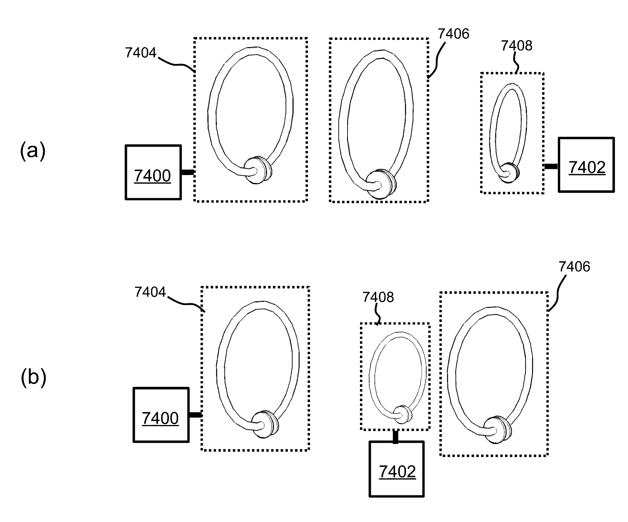
[0415]We disclose examples of high-Q resonators for wireless power transmission systems that may wirelessly power or charge devices at mid-range distances. High-Q resonator wireless power transmission systems also may wirelessly power or charge devices with magnetic resonators that are different in size, shape, composition, arrangement, and the like, from any source resonators in the system.

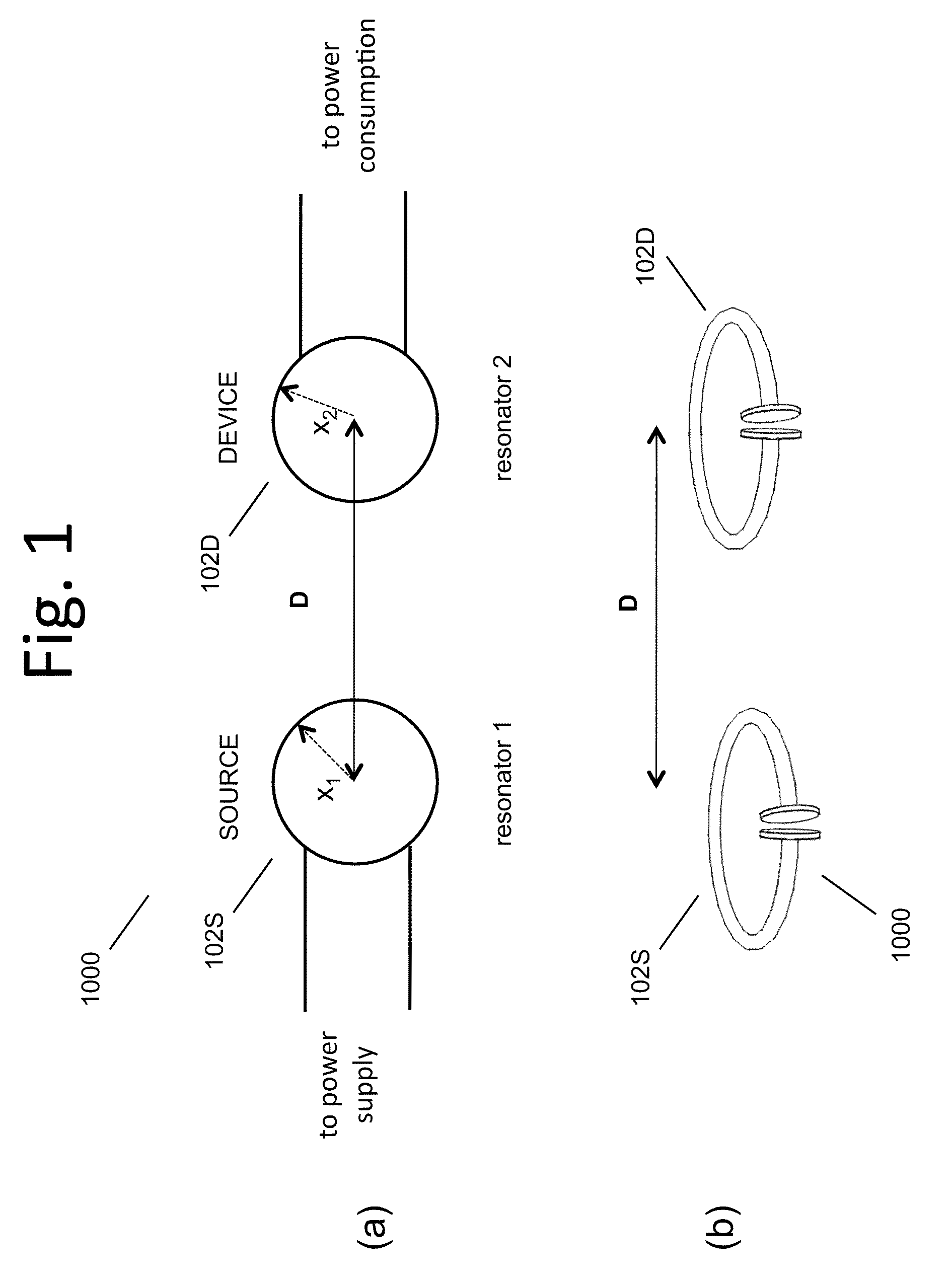
[0416]FIG. 1(a)(b) shows high level diagrams of two exemplary two-resonator systems. These exemplary systems each have a single source resonator 102S or 104S and a single device resonator 102D or 104D. FIG. 38 shows a high level block diagram of a system with a few more features highlighted. The wirelessly powered or charged device 2310 may include or consist of a device resonator 102D, device power and control circuitry 2304, and the like, along with the device 2308 or devices, to which either DC or AC or both AC and DC power is transferred. The energy or power source for a ...


PUM

PropertyMeasurementUnit
sizeaaaaaaaaaa
sizeaaaaaaaaaa
sizeaaaaaaaaaa

Abstract

Described herein are improved configurations for a lighting system with wireless power transfer that includes a source high-Q magnetic resonator coupled to a power source and generating an oscillating magnetic field, at least one device high-Q magnetic resonator configured to convert said oscillating magnetic field to electrical energy used to power a light coupled to the at least one device resonator, and at least one repeater resonator, larger than the device resonator, wherein the repeater resonator is positioned further from the source resonator than the device resonator and improves the power transfer efficiency between the source resonator and the device resonator.

Description

CROSS-REFERENCE TO RELATED APPLICATIONS[0001]This application is a continuation-in-part of U.S. application Ser. No. 12 / 705,582 ('582) filed Feb. 13, 2010 which claims the benefit of U.S. Provisional Application No. 61 / 152,390 filed Feb. 13, 2009.[0002]Application '582 is a continuation-in-part U.S. patent application Ser. No. 12 / 567,716 filed Sep. 25, 2009, which is hereby incorporated by reference in its entirety. U.S. patent application Ser. No. 12 / 567,716 claims the benefit of the following U.S. Patent Applications, each of which is hereby incorporated by reference in its entirety; U.S. App. No. 61 / 100,721 filed Sep. 27, 2008; U.S. App. No. 61 / 108,743 filed Oct. 27, 2008; U.S. App. No. 61 / 147,386 filed Jan. 26, 2009; U.S. App. No. 61 / 152,086 filed Feb. 12, 2009; U.S. App. No. 61 / 178,508 filed May 15, 2009; U.S. App. No. 61 / 182,768 filed Jun. 1, 2009; U.S. App. No. 61 / 121,159 filed Dec. 9, 2008; U.S. App. No. 61 / 142,977 filed Jan. 7, 2009; U.S. App. No. 61 / 142,885 filed Jan. 6, 2...

Claims


Application Information

Patent Timeline
Patent Type & Authority Patents(United States)
IPC IPC(8): H01F27/42H01F38/00H01F37/00
CPCB60L11/182B60L11/1842B60L11/1844B60L11/1846B60L11/1848H02J7/025H03H7/40B60L11/184Y02T90/121B60L2200/12B60L2200/22B60L2210/10B60L2210/20B60L2210/30B60L2210/40B60L2230/22B60L2230/24B60L2250/10B60L2250/16B60L2260/28Y02T10/7088Y02T10/7005Y02T10/7241Y02T10/7216Y02T10/725Y02T90/163Y02T90/169Y02T90/14Y02T90/128Y02T90/127Y02T90/122Y04S10/126Y04S30/14Y02E60/721B60L2200/26B60L53/64B60L55/00B60L53/63B60L53/65B60L53/665B60L53/51B60L53/52H02J7/00034H02J7/35H02J7/34H02J2300/28B60L53/124B60L53/126B60L53/122Y02E60/00Y02T10/70Y02T10/72Y02T10/7072Y02T90/12Y02T90/167H02J50/50H02J50/80H02J50/60H02J50/90H02J50/12H02J50/70Y02T90/16
Inventor GILER, ERIC R.HALL, KATHERINE L.KESLER, MORRIS P.SOLJACIC, MARINKARALIS, ARISTEIDISKURS, ANDRE B.LI, QIANGGANEM, STEVEN J.
Owner WITRICITY CORP
Why Eureka
Try Eureka