Tamper-resistant, energy-harvesting switch assemblies

a technology of energy harvesting switch and switch assembly, which is applied in the direction of tumbler/rocker switch details, contact mechanisms, electrical equipment, etc., can solve the problem of not being widely available for thieves

Active Publication Date: 2013-11-26
JOHNSON MARTIN R +3
View PDF3 Cites 91 Cited by
  • Summary
  • Abstract
  • Description
  • Claims
  • Application Information

AI Technical Summary

Benefits of technology

[0012]The present invention provides a tamper-resistant, longer-lasting energy-harvesting switch assemblies that can also accommodate the longer antennas required for operation in the 315 MHz radio frequency band.

Problems solved by technology

As latch release tools will be sold only in combination with a switch assembly, they will not be generally available for use by thieves.

Method used


Image

  • Tamper-resistant, energy-harvesting switch assemblies
  • Tamper-resistant, energy-harvesting switch assemblies
  • Tamper-resistant, energy-harvesting switch assemblies

Examples


first embodiment

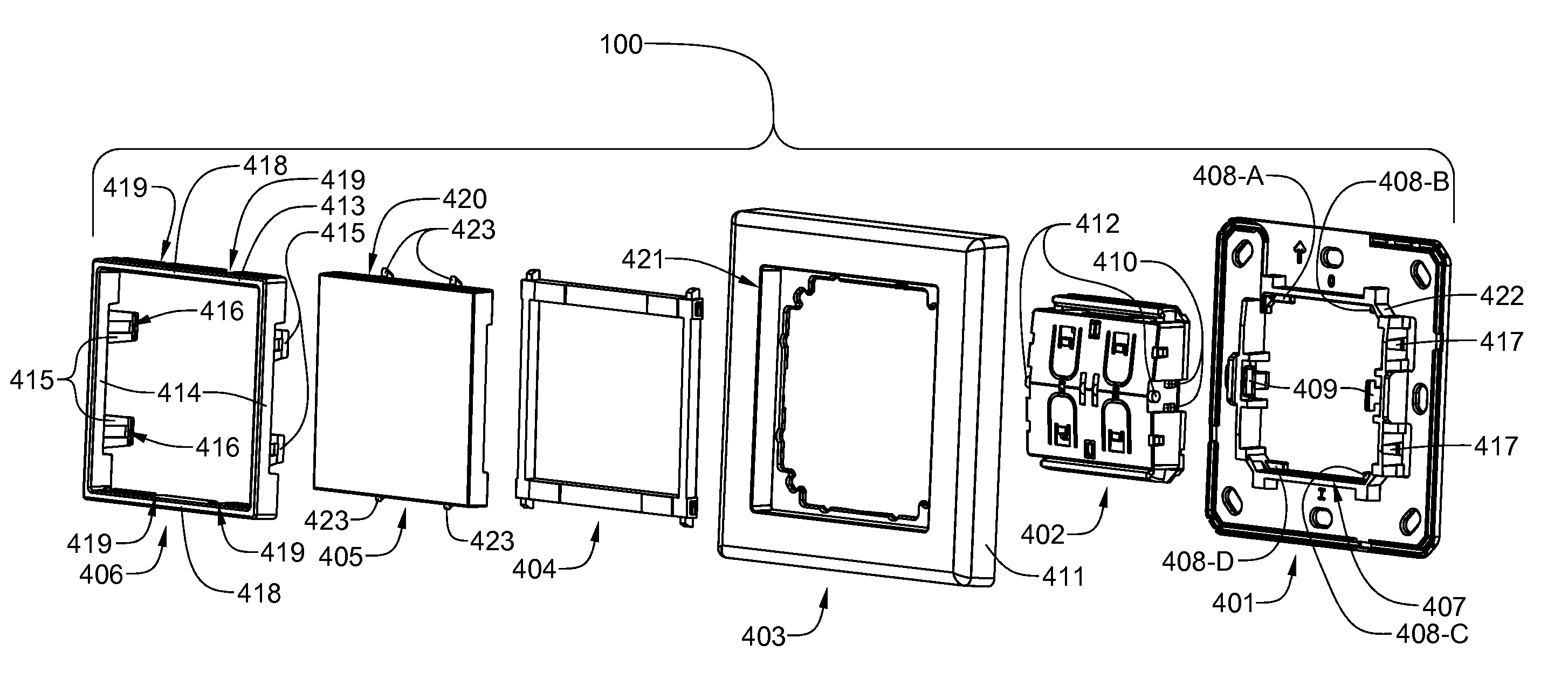
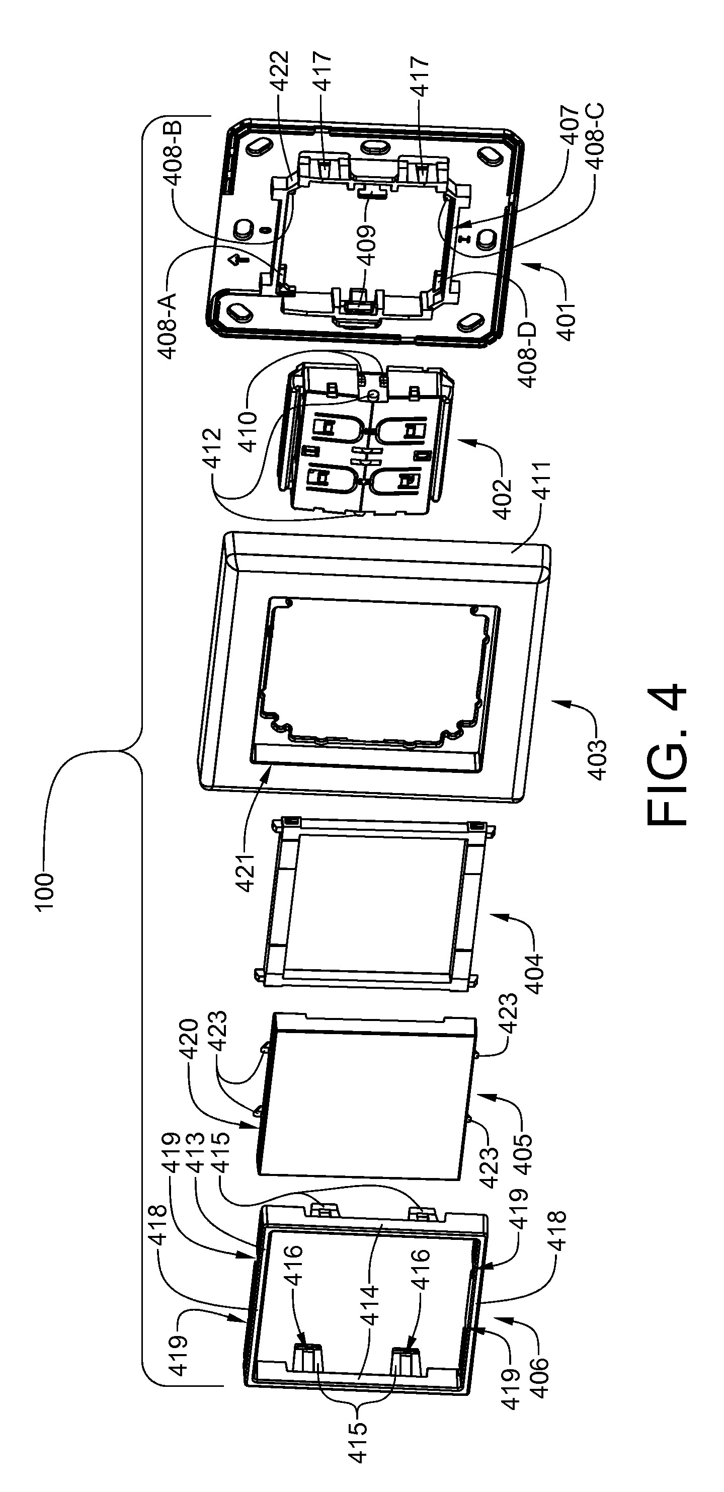
[0053]The various aspects of the invention will be now be described in detail with reference to the attached drawing figures. Drawing FIGS. 1 to 37 cover a surface-mount first embodiment improved single rocker switch assembly that is designed primarily for European applications. In Western Europe internal walls are typically constructed with brick and mortar. Electrical wiring is typically run on the surface of interior walls and outlet and switch boxes are almost always surface mounted.

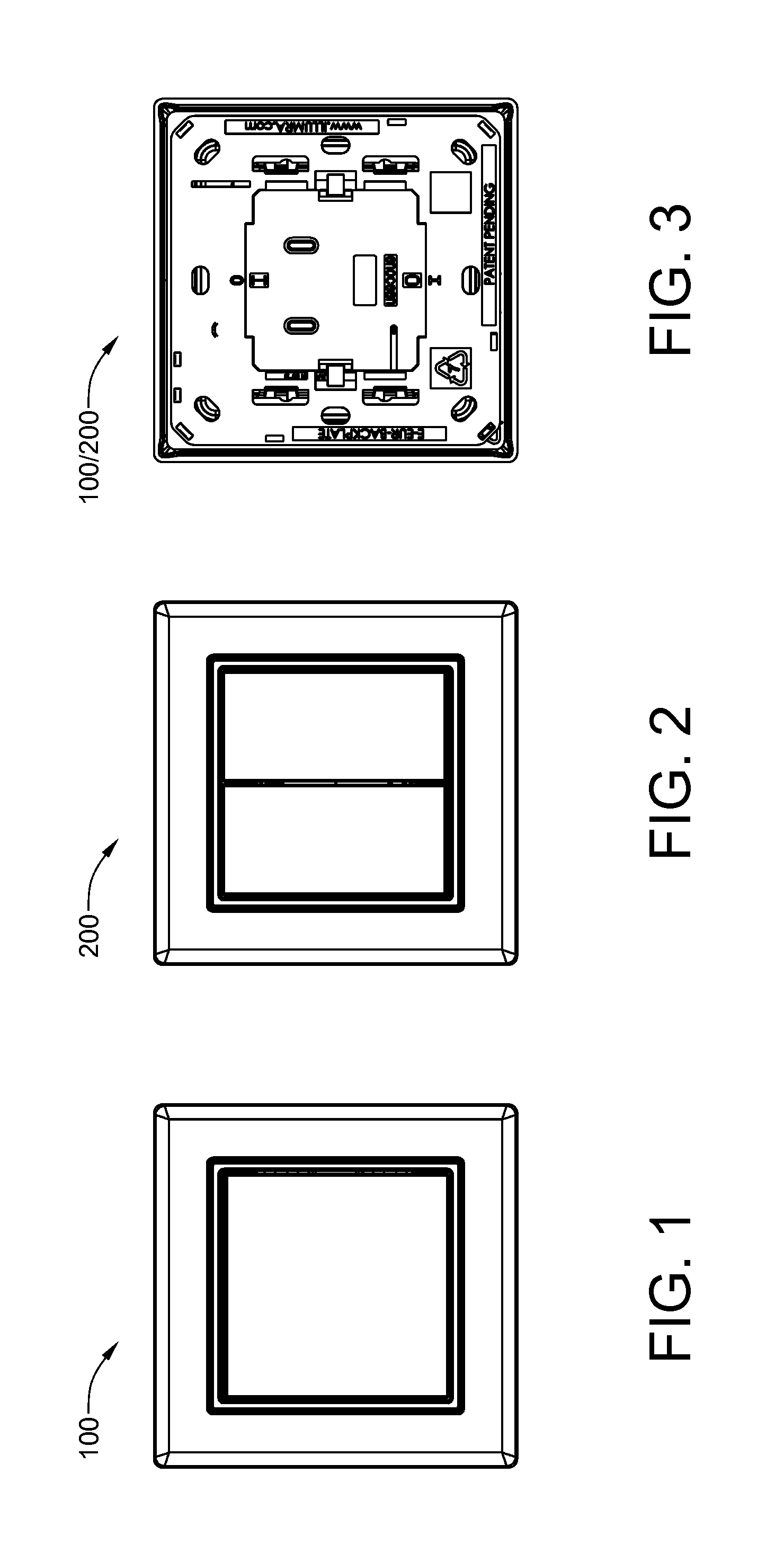
[0054]Referring now to FIG. 1, a surface-mount first embodiment improved single-rocker switch assembly 100 has been designed so that, externally, it is virtually identical to prior-art single-rocker energy-harvesting switch assemblies.

[0055]Referring now to FIG. 2, a surface-mount first embodiment improved double-rocker switch assembly 200 has been designed so that, externally, it is virtually identical to prior-art double-rocker energy-harvesting switch assemblies. In this view, the double rockers, ...

second embodiment

[0078]Referring now to FIG. 33, the individual components shown in FIG. 32 have been assembled into a complete second embodiment, single-rocker, energy-harvesting switch assembly 3300.

[0079]Referring now to FIG. 34, a face plate 3401 has been installed on the second embodiment switch assembly 3300 of FIG. 33. In this view, a second embodiment single rocker 3204 and a second embodiment retainer clip 3205 are also visible.

[0080]Referring now to FIG. 35, the flush-mount second embodiment improved dual-rocker energy-harvesting switch assembly 3500 includes a carrier 3201, an energy harvesting switch module 402, a pair of second embodiment dual-rocker wear inserts 3501-A and 3501-B (which are interchangeable), a pair of second embodiment half-width rockers 3502-A and 3502-B, and a retainer clip 3205. The second embodiment dual-rocker switch assembly 3500 differs from the single-rocker embodiment assembly 3200 only in the design of the double rocker set 3502-A / 3502-B and the wear inserts ...


PUM


Abstract

Tamper-resistant, longer-lasting energy-harvesting switch assemblies that can accommodate longer antennas required for operation in the 315 MHz radio frequency band are provided. In order to accommodate longer antenna that will not fit within the energy-harvesting module, the front major face of the back plate is equipped with a perimetric channel or trough into which a wire antenna can be installed. The problem of rocker wear in prior-art devices caused by abrasive action of the bows is rectified by a redesign of the rocker and the manufacture of a wear-resistant insert that snaps into place at the rear of the rocker. The potential theft problem associated with prior-art devices has been resolved by redesigning the back plate and the retainer clip that engages latches on the redesigned back plate. Non-destructive removal of the retainer clip can be effected only with a special tool.

Description

[0001]This application has a priority date based on Provisional Patent Application No. 61 / 333,079, which has a filing date of May 10, 2010, and is titled TAMPER-RESISTANT, ENERGY-HARVESTING SWITCH ASSEMBLIES.BACKGROUND OF THE INVENTION[0002]1. Field of the Invention[0003]The present invention relates generally, to switch assemblies and, more specifically, to energy-harvesting switch assemblies which convert mechanical energy into electrical energy that is used to generate and transmit radio waves, encoded with circuit control signals, to a remote receiver.[0004]2. History of the Prior Art[0005]It is commonly difficult, costly and / or impractical to install wires between existing controlled electrical systems / circuits and new controlled electrical device(s). The level of difficulty and / or impracticality may be attributable to the need to damage or demolish ceilings, floors, or walls, in order to run control wires. Labor costs for installing new wiring can be considerable. This is part...

Claims


Application Information

Patent Timeline
Patent Type & Authority Patents(United States)
IPC IPC(8): H01H3/00H01H13/00
CPCH01H23/02H01H1/22H01H2239/076
Inventor JOHNSON, MARTIN R.FINLINSON, JAN F.WILLDEN, JEREMY P.GOOCH, ROBERT E.
Owner JOHNSON MARTIN R
Why Eureka
Try Eureka