Non-destructive infrared inspection device

a technology of infrared inspection and inspection device, which is applied in the direction of material analysis, optical radiation measurement, instruments, etc., can solve the problems of composite material component failure, composite material component flaws both at the surface and below the surface of the material, and compromise the strength and durability of the composite componen

Inactive Publication Date: 2006-03-02
THE BOEING CO
View PDF18 Cites 86 Cited by
  • Summary
  • Abstract
  • Description
  • Claims
  • Application Information

AI Technical Summary

Benefits of technology

[0030]FIG. 15 is a diagrammatic environmental view showing an embodiment of the invention that may provide non-destructive inspections of limited clearance structures and conduits which may define pathways having turns and bends;

Problems solved by technology

If surface irregularities and flaws hidden below the surface of a component go undetected, the component may fail.
However, a component constructed of a composite material may have flaws both at the surface and below the surface of the material.
Surface irregularities such as scratches and holes and more hidden irregularities such as cracks, voids, disbonds, and hidden porosities may greatly compromise the strength and durability of a composite component.
Complicating the inspection of aircraft components and parts for other assemblies is the fact that optimized designs often include complex geometries, curved surfaces, and limited access spaces.
Limited-access spaces, such as those enclosed by close-out joints of aircraft wings, are difficult to fully inspect using contemporary inspection devices.
Thus, as typical design optimization processes rely on the assumption that parts are manufactured to exacting specifications, manufacturers face a difficult challenge in identifying parts that fail to meet specifications while controlling manufacturing and maintenance costs.

Method used


Image

  • Non-destructive infrared inspection device
  • Non-destructive infrared inspection device
  • Non-destructive infrared inspection device

Examples


third embodiment

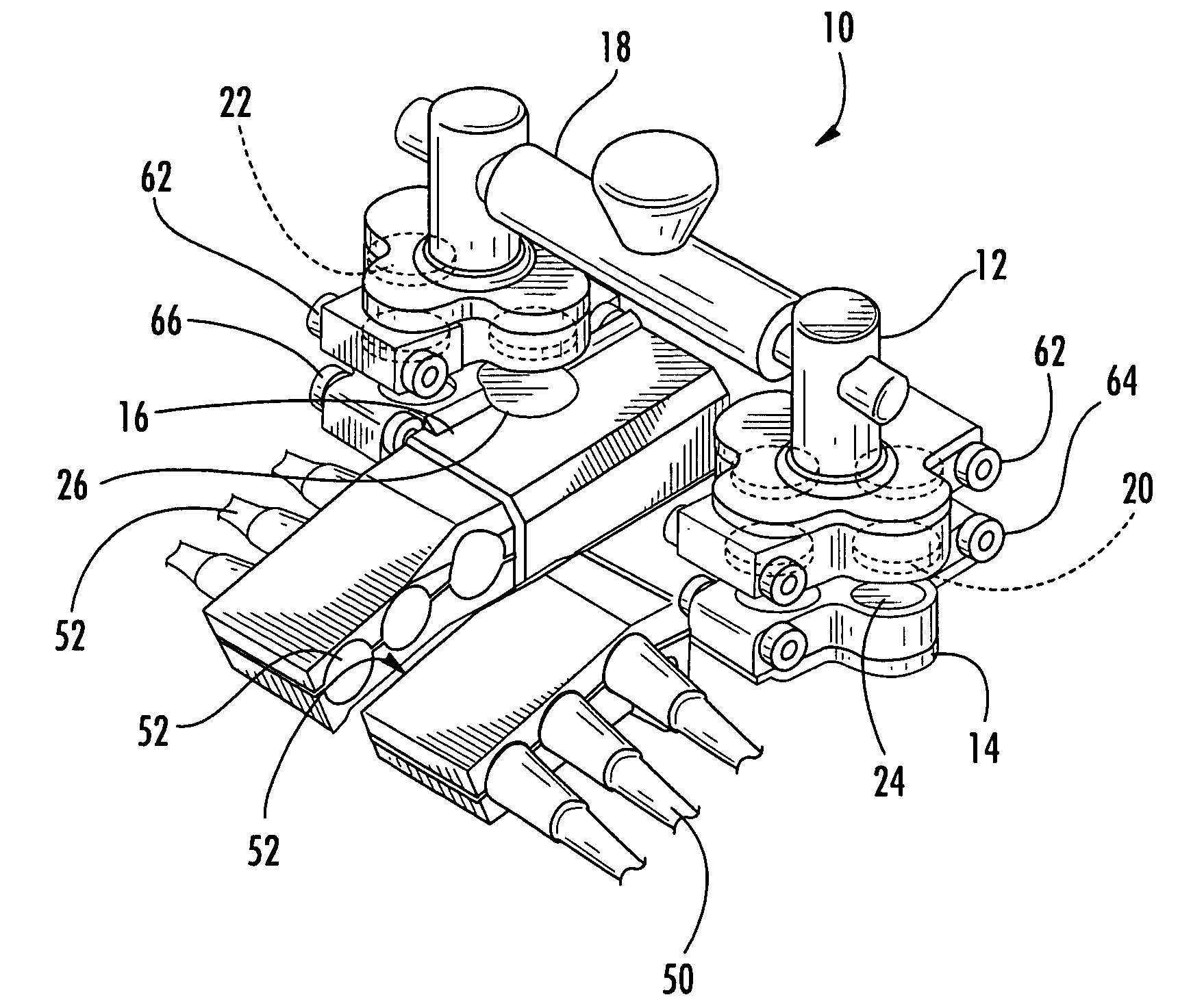
[0052]FIG. 7 illustrates the inspection device 210 that includes a first inspecting portion 214 and second inspecting portion 216, each having a vertical array of inspection sensors 250 and 252, respectively. Vertical arrangement of the inspection sensors 250 and 252 provides for additional inspection data during a single inspection iteration and allows inspection of areas further removed from the actuating portion 212. Further embodiments of the inspection device may have arrays of inspection sensors in any arrangement. Non-limiting examples include the horizontal arrangement shown in FIG. 4 or the angled arrangement shown in FIG. 3. In addition, the inspection sensors may be located on the inspecting portion at any position relative to the magnets of the inspecting portion.

fourth embodiment

[0053]FIG. 8 illustrates the inspection device 310 of the present invention. The inspection device 310 of FIG. 8 comprises only one inspecting portion 314 that further comprises at least one inspection sensor 350 to perform one-sided inspections as described above. In addition, the inspection sensors 350 of FIG. 8 comprise wireless data transmission either directly or indirectly to the processing element. Examples of such wireless data communication include, but are not limited to, WiFi applications, Bluetooth applications, or other wireless LAN applications known in the art.

[0054] As detailed in the following descriptions with reference to at least FIGS. 9-18, a structure may be subjected to non-destructive inspection by use of an infrared sensor that detects infrared light radiating from the structure. Optionally, an infrared sensor collects data for infrared imaging and infrared thermography. Inspections without couplants, single-sensor multiple-sensor inspections, one-sided insp...


PUM

PropertyMeasurementUnit
long-wavelength aaaaaaaaaa

Abstract

There is provided a non-destructive inspection device having an infrared sensor for infrared thermography inspection of a structure or surface. A rotatable reflector reflects infrared light from an inspected surface to an infrared sensor. An inspecting portion of a non-destructive device is magnetically coupled to an actuating portion of the device for concerted movement of the portions. An inspection device includes both an infrared sensor for infrared imaging and an optical device such as a camera for visible light imaging.

Description

CROSS-REFERENCE TO RELATED APPLICATIONS [0001] This application is a continuation-in-part, and claims the benefit of priority to, co-pending U.S. non-provisional patent application No. 10 / 752,890 of Bossi et al., filed Jan. 7, 2004, which co-pending patent application and the publication thereof, namely United States patent application publication number US2005 / 0145033A1, published Jul. 7, 2005, are incorporated herein by reference.FIELD OF THE INVENTION [0002] Embodiments of the present invention relate generally to non-destructive inspection devices. More particularly, embodiments of the invention relate to devices for the infrared inspection of a structure. BACKGROUND OF THE INVENTION [0003] Manufacturers often optimize the designs of parts that they manufacture in efforts to increase the efficiencies of devices and structures in which the parts are used. Designs are often optimized through the use of light-weight materials and by the minimization of the amounts of materials used...

Claims


Application Information

Patent Timeline
Patent Type & Authority Applications(United States)
IPC IPC(8): G01N21/88
CPCG01N21/954G01N21/9515
Inventor SAFAI, MORTEZAGEORGESON, GARY E.
Owner THE BOEING CO
Why Eureka
Try Eureka