High Speed Metrology with Numerically Controlled Machines

a numerical control machine and high-speed technology, applied in the field of synchronizing, logging and post-processing metrology instrument readings, can solve the problems of difficult to produce cnc machine tools that are capable of high, inability to ensure the accuracy of workpieces, and inability to accurately match workpieces, etc., to achieve high-quality workpiece verification, ensure production tolerances, and improve the effect of accuracy

Active Publication Date: 2014-06-12
GRALE TECH
View PDF16 Cites 89 Cited by
  • Summary
  • Abstract
  • Description
  • Claims
  • Application Information

AI Technical Summary

Benefits of technology

[0017]One result is to enable or speed up automated setup, which may include establishing a workpiece coordinate system and its detailed maximum material condition prior to initializing the production operation. Another result is a highly accurate verification of a workpiece after or between the production steps. The measurements are provided to the machine prior to breaking setup. Such measurements enable the closed-loop control of the precision production equipment without breaking setup and re-establishing the part coordinate system. Such in-situ verification enables substantially complete serialized dimensional quality control of each workpiece. Production tolerances are ensured and continuously improved. Workpieces are produced and verified to match design assembly dimensions within tight tolerances. Multiple component matching may be performed based on serialized quality control data yielding assemblies with tighter stack-up tolerances. Machine drift may be characterized and corrected throughout daily, weekly and monthly production cycles.
[0018]Still another result is to enable the three dimensional surface, sub-surface and through-bod...

Problems solved by technology

However, it is difficult to produce CNC machine tools that are capable of high fidelity measurements of said workpiece with absolute accuracy on the order of micrometers (10−4 inches).
Such setup can be tedious and time-consuming for large geometrically complex parts such as castings and weldments.
Further, just after the product or workpiece is created, it is unknown whether the particular workpiece matches in all respects the drawing or digital model.
For example, taking such measurements over the surface of most shapes and workpieces is time-consuming.
Further, the stylus ball at the end of the touch probe inherently limits the minimum feature size tactile feedback is capable of, certainly compared to other means of measurement (e.g., laser sensors, optical sensors).
Only a limited number of measurements are realistically possible with discrete tactile measurements as determined by the time budget for inspection and the average time between touch probe operations.
The variability involved with establishing the part coordinate system multiple times in multiple machines creates a source of error if and when the same component requires rework in the production equipment.
When rework is required, the accuracy requirements of the subsequent set up in the production equipment are increased significantly and may require even more care and time to achieve the part coordinate system and maximum material con...

Method used


Image

  • High Speed Metrology with Numerically Controlled Machines
  • High Speed Metrology with Numerically Controlled Machines
  • High Speed Metrology with Numerically Controlled Machines

Examples


Embodiment Construction

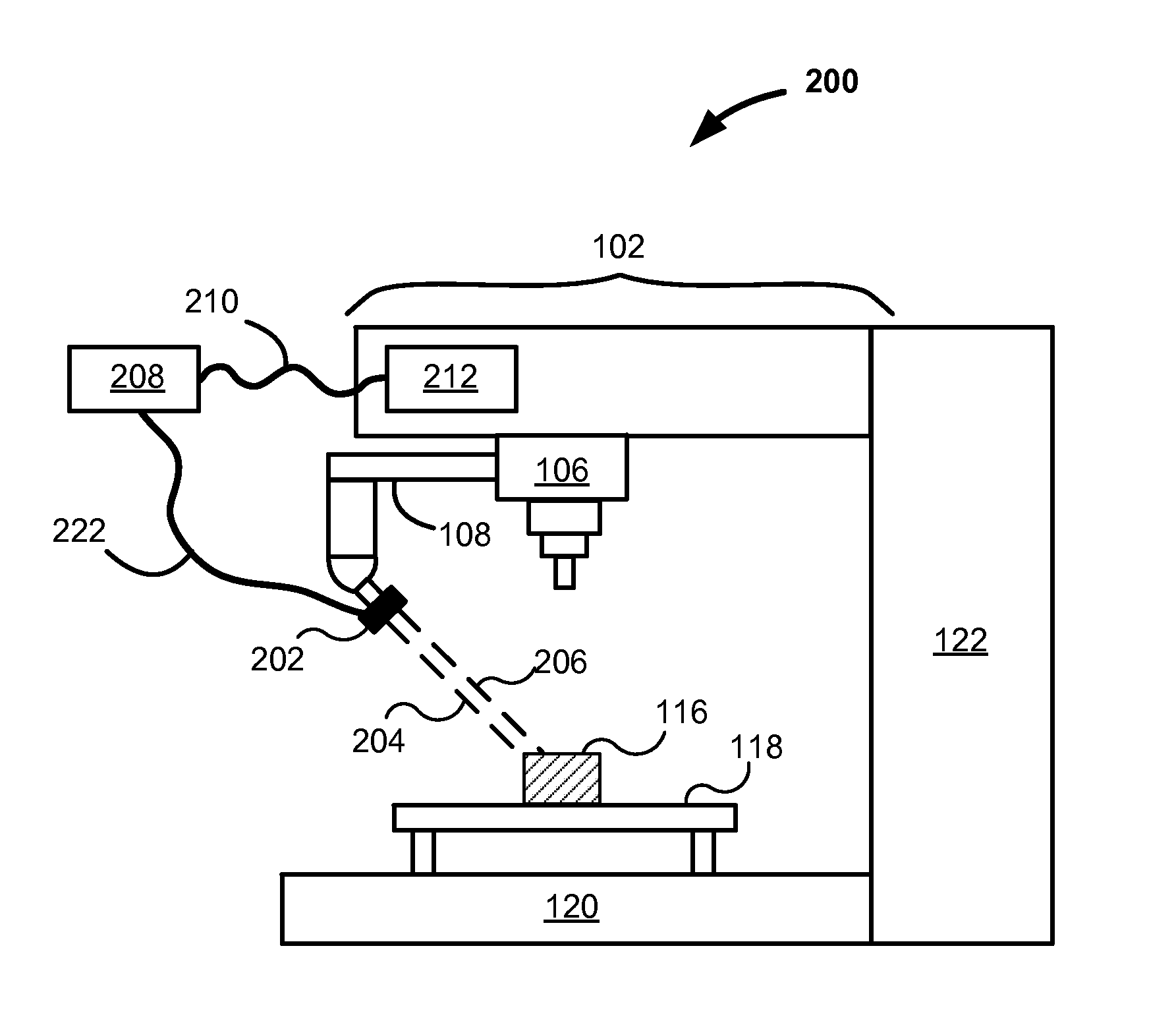
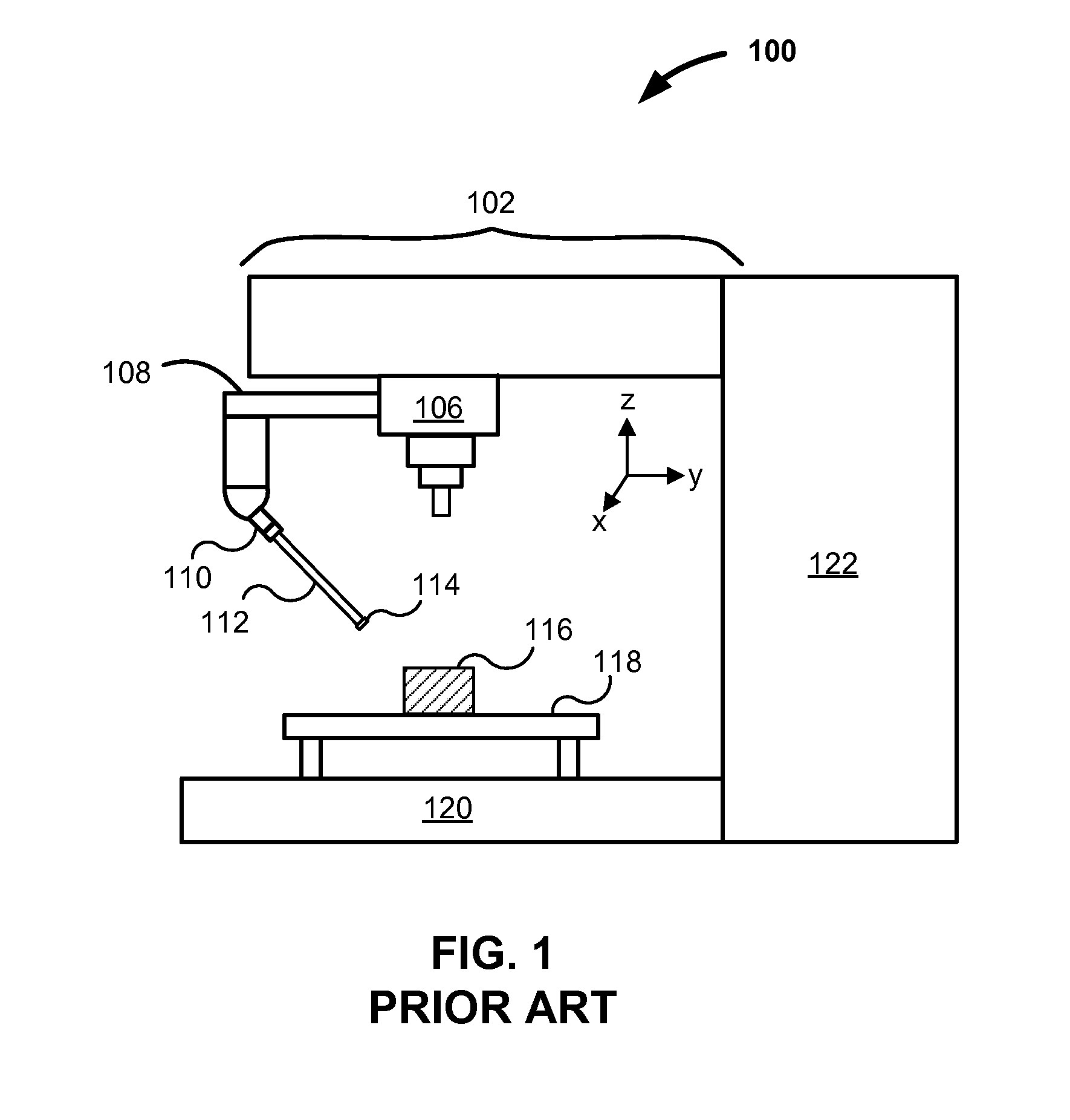
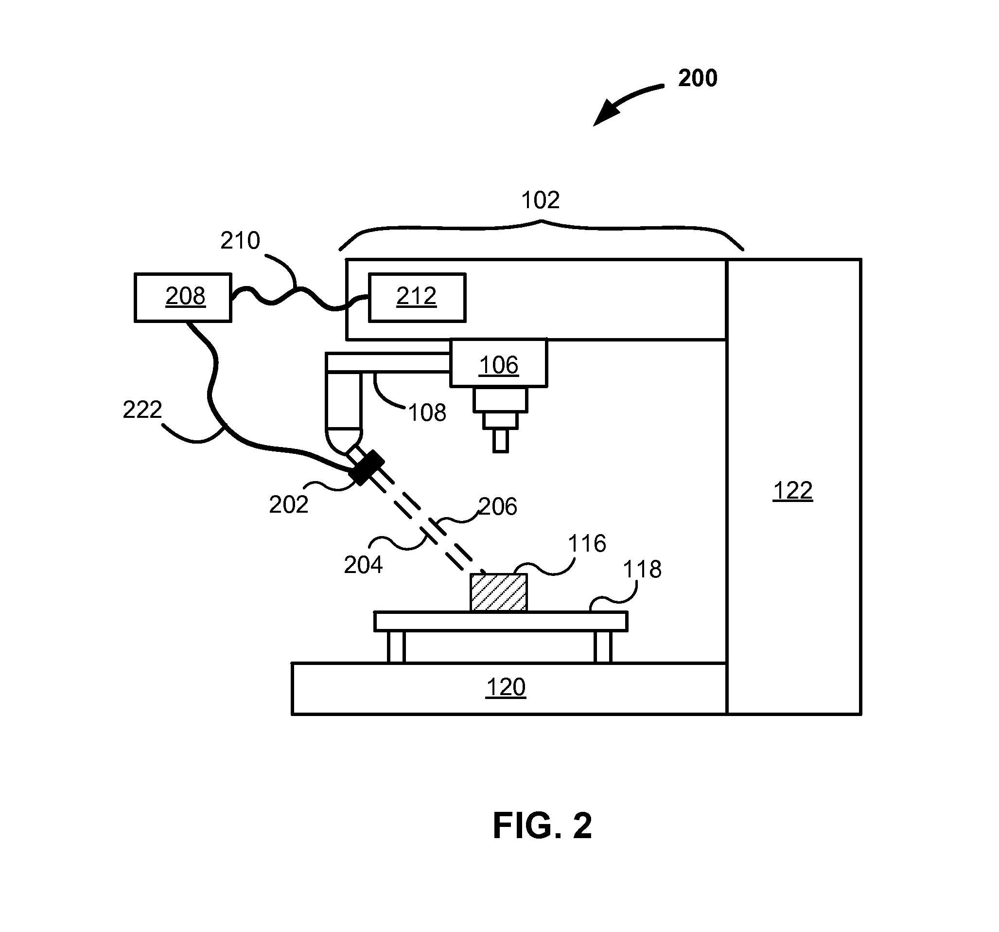
[0034]Overview. Precision production equipment and measure machines have been used for many years to make two-dimensional and three-dimensional workpieces from solid blanks or blocks of a starting material. Material is removed little by little until the final workpiece remains. Milling machines come in a variety of sizes. Milling machines can move a spindle, arm or tool relative to the workpiece, or can move the workpiece relative to the spindle, arm or tool. Often, the milling tool is a rotating milling cutter, which cuts on the tool's sides and tip. While some milling machines are manually operated, most modernized milling machines are computer controlled. Such control is often referred to as computer numerically controlled (CNC). While a CNC machine may be referenced herein, such referenced machine is not limited to just milling machines, but refers generally to all precision production equipment.

[0035]A workpiece is often created from a model or digital design. An operator, prog...


PUM


Abstract

Systems, apparatuses and methods are described for integrating an electronic metrology sensor with precision production equipment such as computer numerically controlled (CNC) machines. For example, a laser distance measuring sensor is used. Measurements are taken at a relatively high sample rate and converted into a format compatible with other data generated or accepted by the CNC machine. Measurements from the sensor are synchronized with the position of the arm of the machine such as through the use of offsets. Processing yields a detailed and highly accurate three-dimensional map of a workpiece in the machine. Applicable metrology instruments include other near continuously reading non-destructive characterization instruments such as contact and non-contact dimensional, eddy current, ultra-sound, and X-Ray Fluorescence (XRF) sensors. Various uses of measurements include: multiple component matching, correction of machine drift, closed loop control of machines, and verification of product tolerances via substantially complete serialized dimensional quality control.

Description

BACKGROUND OF THE INVENTION[0001]1. Field[0002]The present invention relates to synchronizing, logging and post processing metrology instrument readings with the position and orientation of precision production equipment such as: computer numerically controlled (CNC) mills and lathes, grinding machines, lapping machines, robots, additive manufacturing equipment (a partial list of precision production equipment). More particularly, as an example, the invention relates to synchronizing non-contact dimensional metrology instruments with precision production equipment in order to characterize a workpiece's shape and features while it is loaded in the work space of precision production equipment.[0003]2. Related Art[0004]At the time of writing, a computer numerically controlled (CNC) machine is capable of manufacturing a workpiece or product to within 2 micrometers (10−4 inches) of design specifications under close to ideal conditions. Some precision production equipment can achieve even...

Claims


Application Information

Patent Timeline
IPC IPC(8): G01B21/16
CPCG01B21/04G01B21/16G05B19/401G05B2219/37198Y02P80/40
Inventor GARVEY, MICHAELOSTERLOH, JAMES D.PERSI, FRED
Owner GRALE TECH
Why Eureka
Try Eureka