Holographic projection device for the reconstruction of scenes

a projection device and scene technology, applied in the field of scene reconstruction, can solve the problems of limited movement freedom of observers limited size of the reconstruction scene, etc., and achieve the effect of improving image quality

Active Publication Date: 2013-11-26
SEEREAL TECHNOLOGIES
View PDF7 Cites 3 Cited by
  • Summary
  • Abstract
  • Description
  • Claims
  • Application Information

AI Technical Summary

Benefits of technology

[0016]It is advantageous if the holographic projection device is anamorphic, i.e. if it exhibits different magnification in two directions which are perpendicular to each other and perpendicular to the direction of light propagation. This is important for the wave front modulated by the modulation elements to propagate to, i.e. to be imaged to, the same position in an observer plane, for example to a virtual observer window where at least one observer eye is located, if the light modulator device is scanned line by line. This helps to prevent the light from being vignetted. The same applies accordingly if the light modulator device is scanned column by column. Another advantage is that an enlargement of the observer window in the scanning direction, which is also referred to as the non-coher

Problems solved by technology

The size of the reconstructed scene is limited by the size of the field lens.
Further, the observer of the reconstructed scen

Method used


Image

  • Holographic projection device for the reconstruction of scenes
  • Holographic projection device for the reconstruction of scenes
  • Holographic projection device for the reconstruction of scenes

Examples


Embodiment Construction

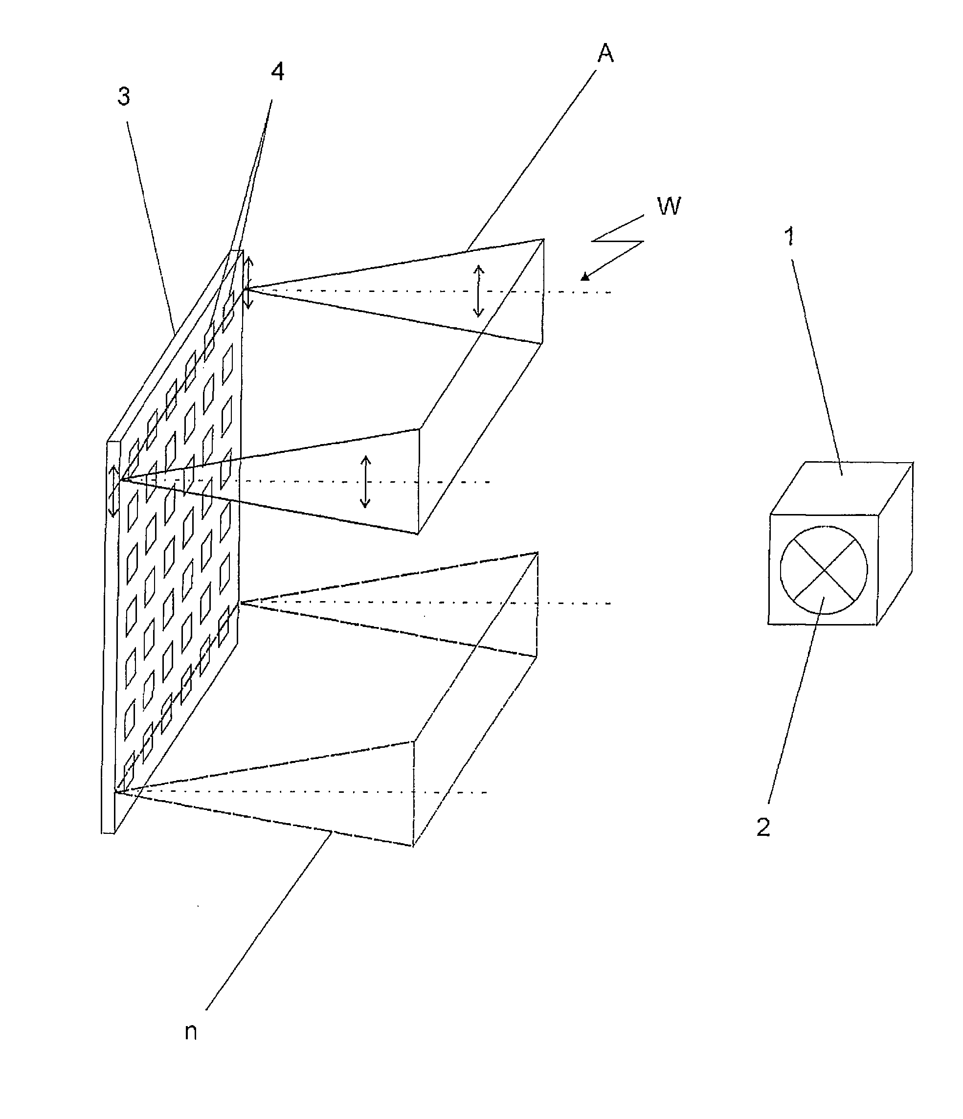
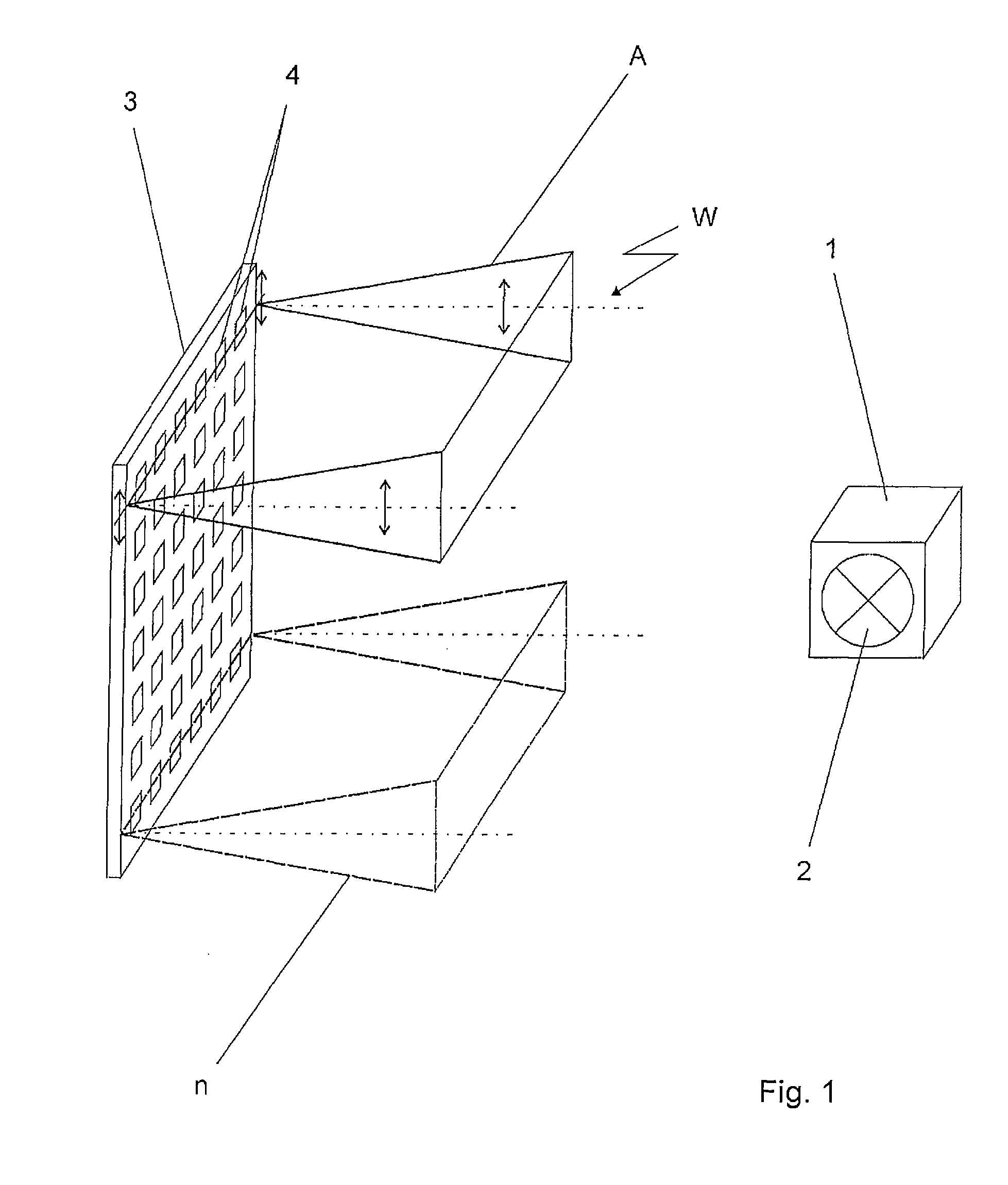
[0042]FIG. 1 shows an illumination device 1 with a light source 2 for illuminating a light modulator device 3. The illumination device 1 and the light modulator device 3 are disposed at certain positions in the holographic projection device. However, this arrangement is only explained in FIG. 5. The light source 2 emits sufficiently coherent light. In this document, the term ‘sufficiently coherent light’ denotes light which is capable of generating interference for the holographic reconstruction of a three-dimensional scene. The light source 2 of the illumination device 1 can be made of laser diodes, DPSS lasers (diode-pumped solid state lasers) or other lasers. Other light sources, e.g. LED (light emitting diodes), can be used as well as long as they emit sufficiently coherent light. However, such light sources should be filtered so as to achieve a sufficient degree of coherence.

[0043]This Figure shows in detail how the light modulator device 3 is scanned by a scanning element (not...


PUM


Abstract

A holographic projection device comprises for the reconstruction of scenes at least one light source which emits sufficiently coherent light for the generation of a wave front. Further, the projection device comprises at least one light modulator device containing modulation element, said projection device being of a two-dimensional design. The light modulator device and a scanning element are combined such that the light emitted by the scanning element only scans one one-dimensional arrangement of modulation elements of the two-dimensional light modulator device at a time.

Description

CROSS REFERENCE TO RELATED APPLICATIONS[0001]This application claims the priority of PCT / EP2007 / 054781, filed on May 16, 2007, which claims priority to DE 10 2006 024356.0, filed May 19, 2006, the entire contents of which are hereby incorporated in total by reference.FIELD OF THE INVENTION[0002]The present invention relates to a holographic projection device for the reconstruction of scenes, said device comprising at least one light source which emits sufficiently coherent light which is used to generate a wave front, and at least one two-dimensional light modulator device which comprises modulation elements. The invention further relates to a method for the holographic reconstruction of scenes.BACKGROUND OF THE INVENTION[0003]It is commonly known to use holographic techniques in order to reproduce a real three-dimensional scene of an object, said scene containing all depth information which is used by the human brain in image processing. Holography is a technique for recording and ...

Claims


Application Information

Patent Timeline
IPC IPC(8): G02B5/32G03H1/16G03H1/12
CPCG03H1/2294G03H2001/221G03H2001/2292G02B26/00G02B27/18G03B21/00G03H1/04
Inventor RENAUD-GOUD, PHILIPPE
Owner SEEREAL TECHNOLOGIES
Why Eureka
Try Eureka