Method for measuring the temperature rise induced by bias current/bias voltage in a magnetic tunnel junction

a tunnel junction and bias current technology, applied in the direction of heat measurement, magnetic bodies, instruments, etc., can solve the problems of serious influence on the working performance of the magnetic head, high temperature noise, and high temperature noise, and achieve stable and reliable reading performance.

Active Publication Date: 2013-11-26
SAE MAGNETICS (HK) LTD
View PDF5 Cites 2 Cited by
  • Summary
  • Abstract
  • Description
  • Claims
  • Application Information

AI Technical Summary

Benefits of technology

[0009]One objective of the present invention is to provide a method for measuring the temperature rise induced by bias current / bias voltage in a magnetic tunnel junction of a tunnel magnetoresistive sensor; thereby it can be determined what kind of reader design can provide more stable and reliable reading performance especially under higher operational temperature.
[0018]In comparison with the prior art, the present invention provides a method for measuring the temperature rise induced by bias current / bias voltage in a magnetic tunnel junction of a tunnel magnetoresistive (TMR) sensor, thereby it can be determined what kind of TMR reader design can provide more stable and reliable reading performance especially under higher operational temperature.

Problems solved by technology

However, high temperature noise (HTN) problems always exist in the above-mentioned MR sensors and influence their working performance seriously.
As well known, higher bias current / bias voltage is needed to provide better performance of the MR sensor, but higher bias current / bias voltage applied will bring higher temperature rise, in turn, induce high temperature noise.
However, the TMR sensor does not belong to conductor, above-mentioned conductor's method can not be implemented for a TMR sensor so as to measuring the temperature rise in its magnetic tunnel junction (MTJ).

Method used


Image

  • Method for measuring the temperature rise induced by bias current/bias voltage in a magnetic tunnel junction
  • Method for measuring the temperature rise induced by bias current/bias voltage in a magnetic tunnel junction
  • Method for measuring the temperature rise induced by bias current/bias voltage in a magnetic tunnel junction

Examples


Embodiment Construction

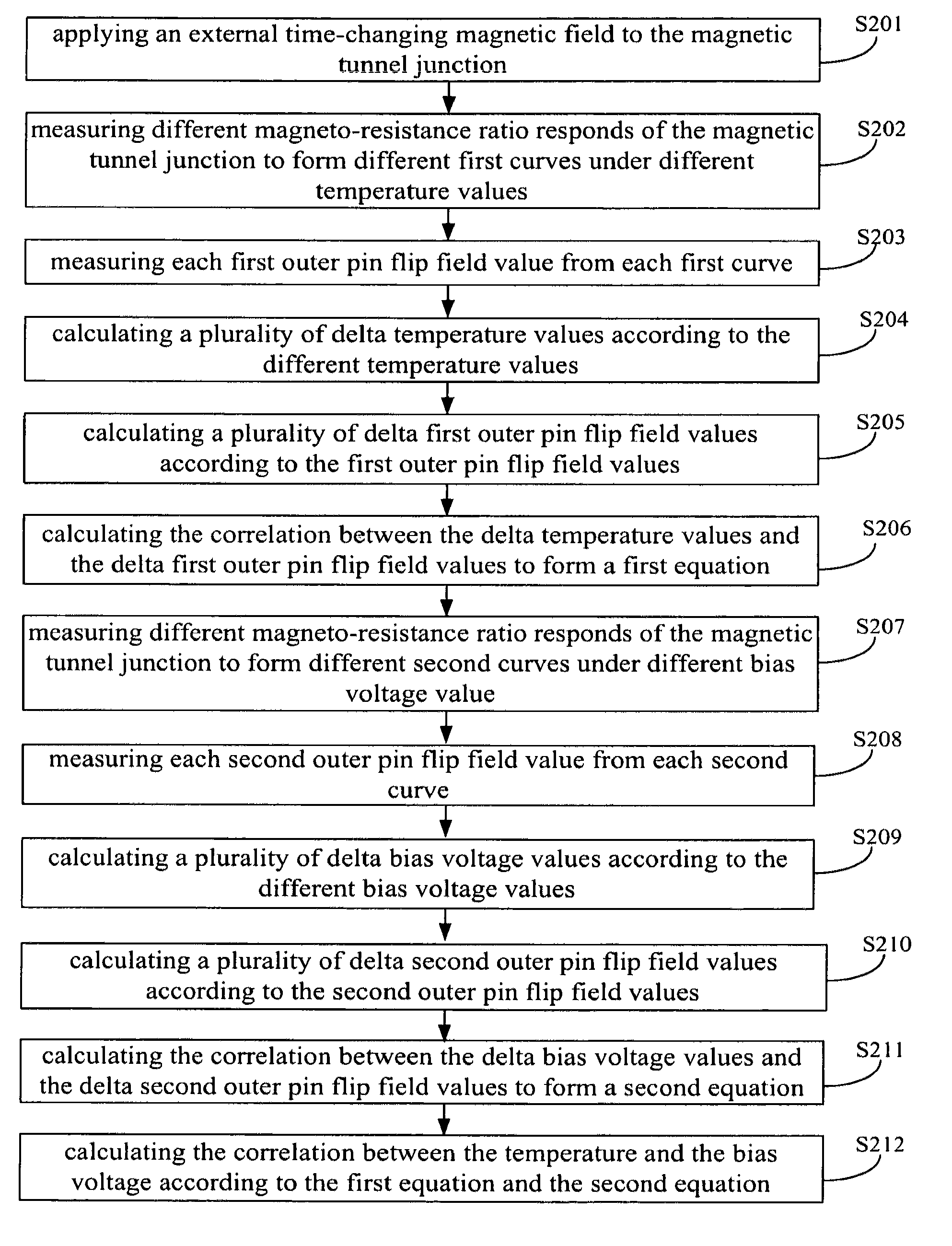
[0033]Various preferred embodiments of the invention will now be described with reference to the figures, wherein like reference numerals designate similar parts throughout the various views. As indicated above, the invention is directed to a method for measuring the temperature rise induced by bias current / bias voltage in a magnetic tunnel junction. The method includes the steps of: (a) applying an external time-changing magnetic field to the magnetic tunnel junction; (b) measuring different first outer pin flip field values under different temperature values; (c) calculating the correlation between the temperature and the outer pin flip field according to the temperature values and the first outer pin flip field values; (d) measuring different second outer pin flip field values under different bias current / bias voltage values; (e) calculating the correlation between the bias current / bias voltage and the outer pin flip field according to the bias current / bias voltage values and the...


PUM

PropertyMeasurementUnit
bias voltageaaaaaaaaaa
applied bias voltageaaaaaaaaaa
magnetization angleaaaaaaaaaa

Abstract

A method for measuring a temperature rise induced by bias current / bias voltage in a magnetic tunnel junction includes: (a) applying an external time-changing magnetic field to the magnetic tunnel junction; (b) measuring different first outer pin flip field values under different temperature values; (c) correlating the temperature values with the outer pin flip field values; (d) measuring different second outer pin flip field values under different bias current / bias voltage values; (e) correlating the different bias current / bias voltage-values with the measured different second outer pin flip field values; and (f) correlating temperature values and bias current / bias voltage values according to the results produced by (c) and (e). The method can determine what kind of TMR reader design provides more stable and reliable reading performance, especially under higher operational temperatures.

Description

[0001]This application claims the benefit of Chinese Patent Application No. 201010588666.5, filed 15 Dec. 2010, the entire contents of which is hereby reference in this application.FIELD OF THE INVENTION[0002]The present inventions relates to methods for testing the performance of a magnetic head, and more particularly to a method for measuring the temperature rise induced by bias current / bias voltage in a magnetic tunnel junction (MTJ).BACKGROUND OF THE INVENTION[0003]Hard disk drive incorporating rotating magnetic disks is commonly used for storing data in the magnetic media formed on the disk surfaces, and a movable slider including read sensors are generally used to read data from tracks on the disk surfaces.[0004]Presently, magnetoresistive (MR) read sensor, commonly referred to as MR sensor, is the prevailing read sensor because of its better capability to read data from a surface of a disk at greater track and linear densities than thin film inductive heads. An MR sensor dete...

Claims


Application Information

Patent Timeline
Patent Type & Authority Patents(United States)
IPC IPC(8): G01K7/00G01K7/36
CPCB82Y25/00G01K7/36G01K13/10G01K15/005G01R33/098G01R33/007G01K2217/00H01F10/3254
Inventor LEE, MANKITLUENG, CHIUMINGLEUNG, CHEUKWINGDING, JURENNI, RONGKWANG
Owner SAE MAGNETICS (HK) LTD
Why Eureka
Try Eureka