Installation structure of a pedal stroke sensor

a technology of installation structure and pedal stroke, which is applied in the direction of mechanical control devices, instruments, process and machine control, etc., to achieve the effect of detecting the deflection angle of the pedal with ease and accuracy

Active Publication Date: 2013-12-03
MITSUBISHI MOTORS CORP
View PDF23 Cites 0 Cited by
  • Summary
  • Abstract
  • Description
  • Claims
  • Application Information

AI Technical Summary

Benefits of technology

[0012]It is an object of the invention to provide an installation structure of a pedal stroke sensor, which enables even a pedal stroke sensor placed far away from a pedal to detect a pedal deflection angle with ease and accuracy.
[0014]By employing such a link mechanism, the pedal deflection can be easily transmitted to the pedal stroke sensor even if the pedal stroke sensor is placed far away from the pedal. The link mechanism is moreover capable of transmitting displacement without causing backlash. Even if the pedal stroke sensor is placed away from the pedal, there occurs no position gap of the pedal, which triggers an error.
[0015]Consequently, even the pedal stroke sensor placed far away from the pedal is capable of detecting the pedal deflection angle with ease and accuracy.

Problems solved by technology

Even if the pedal stroke sensor is placed away from the pedal, there occurs no position gap of the pedal, which triggers an error.

Method used


Image

  • Installation structure of a pedal stroke sensor
  • Installation structure of a pedal stroke sensor
  • Installation structure of a pedal stroke sensor

Examples


Embodiment Construction

[0021]The present invention will be described below on the basis of one embodiment shown in FIGS. 1 to 3.

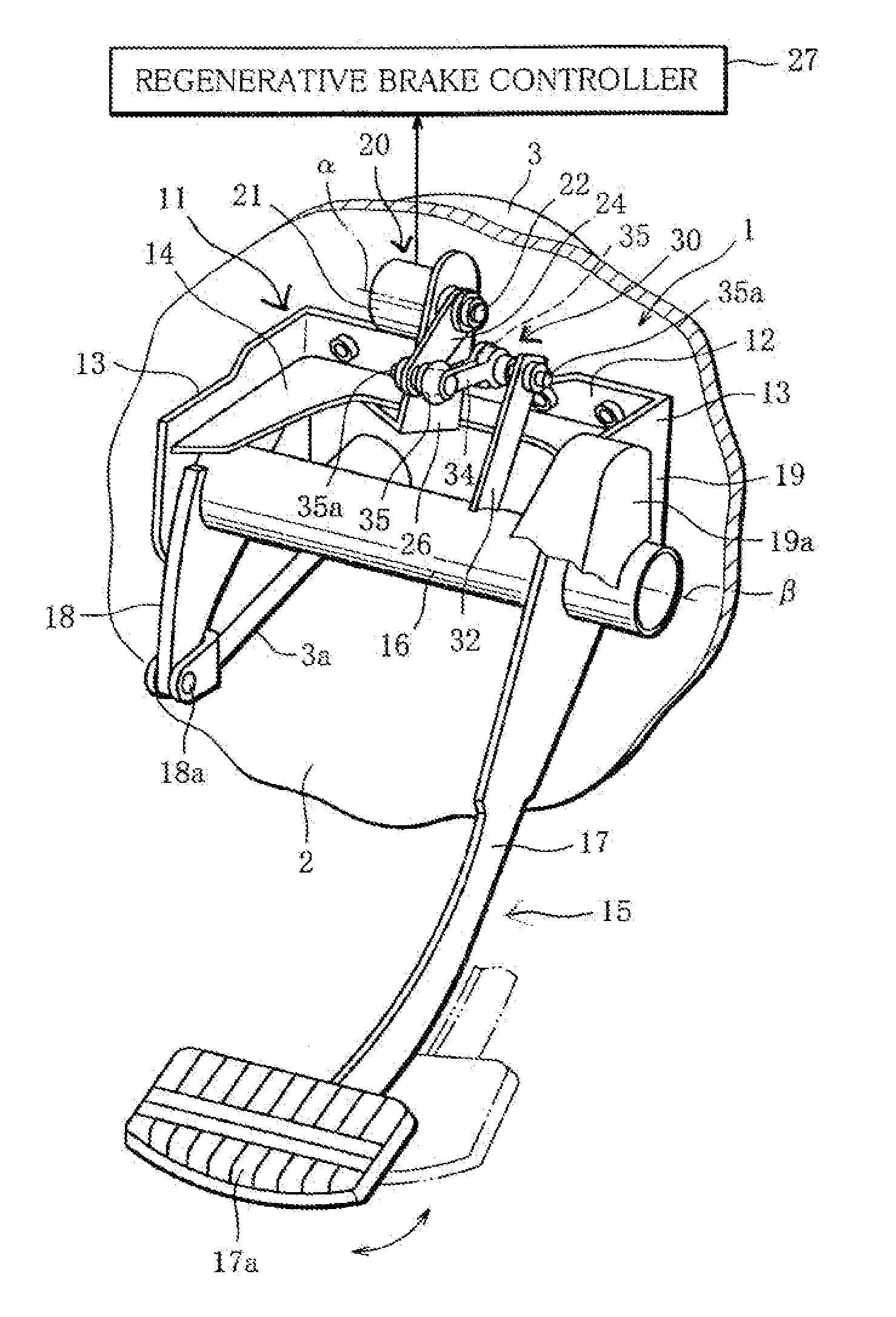
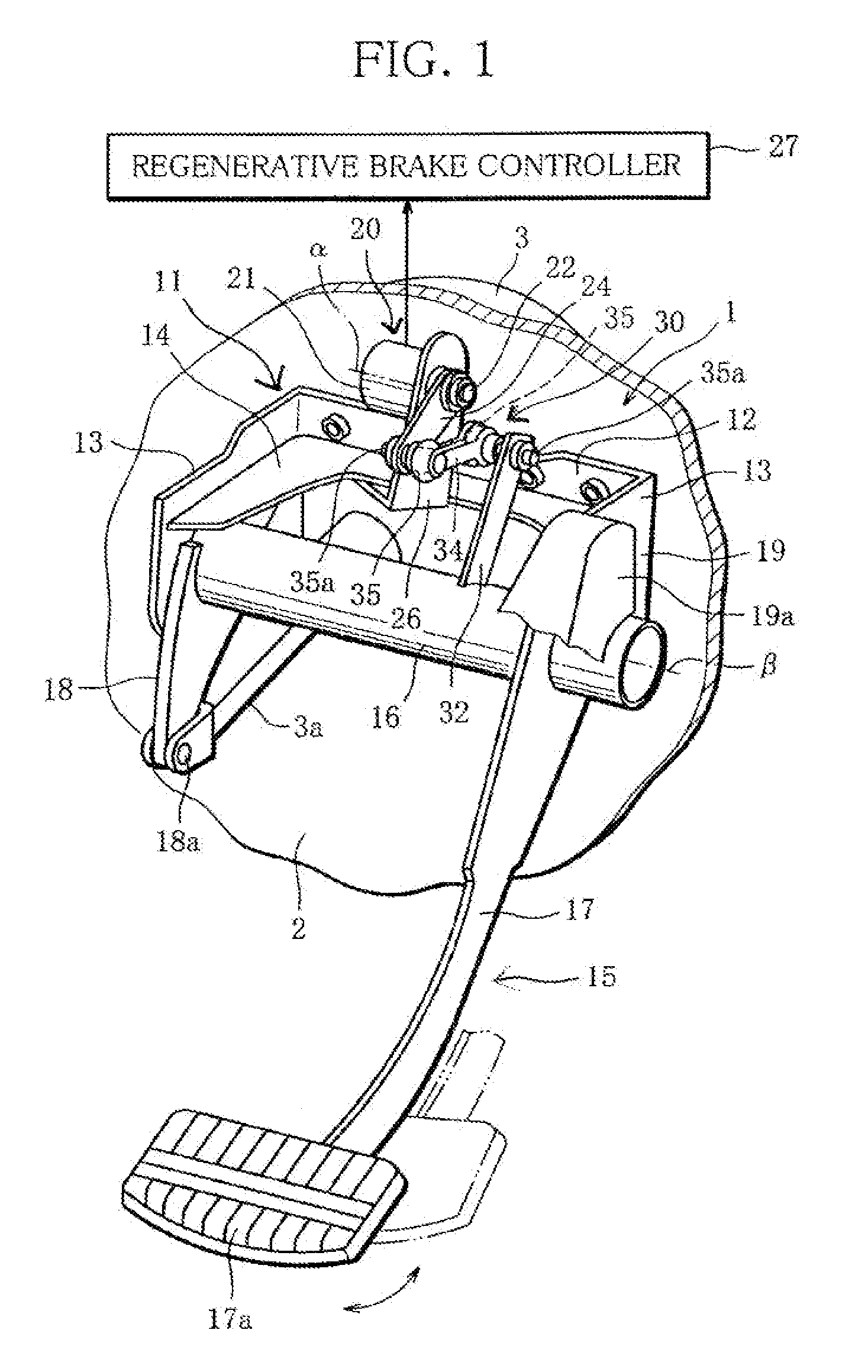
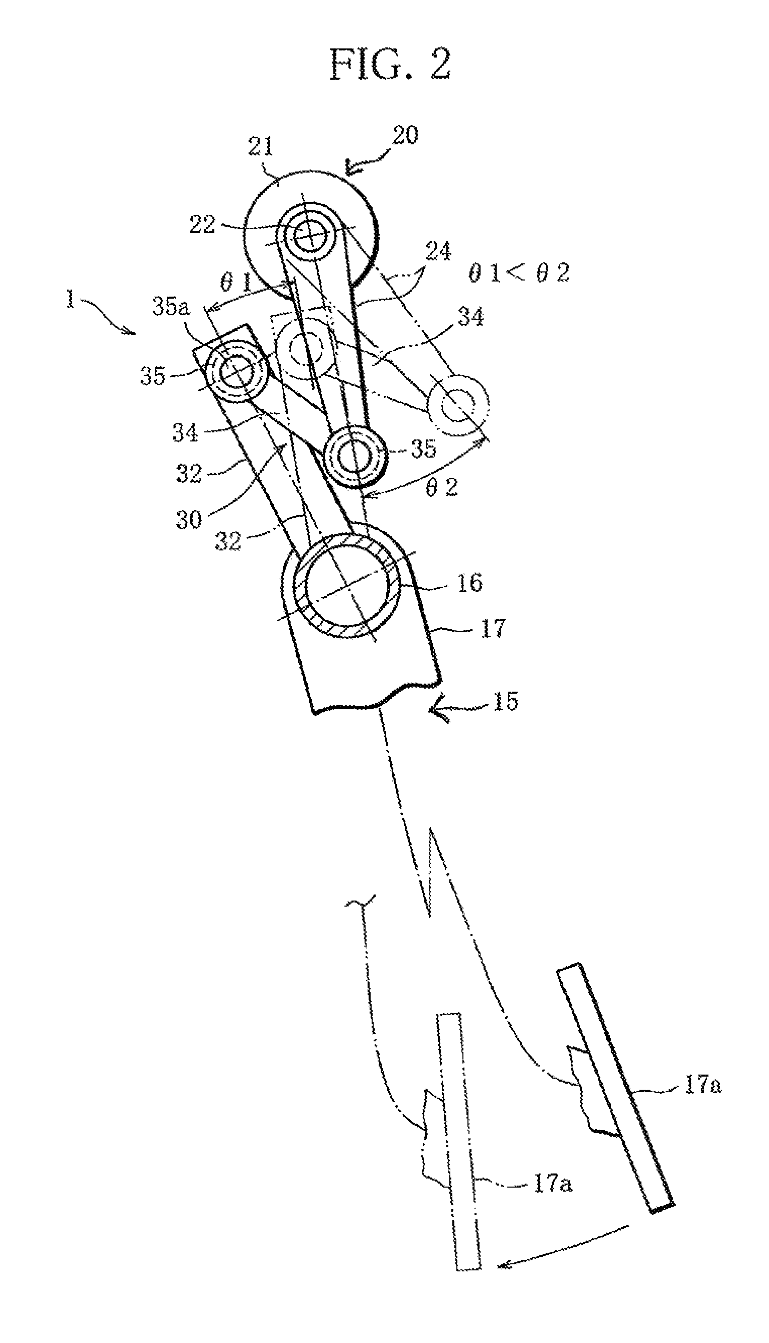
[0022]FIG. 1 is a perspective view showing a brake pedal unit 1 that is installed under the driver's seat of a vehicle, for example, an electric vehicle. FIG. 2 is a sectional side view of the brake pedal unit 1.

[0023]As illustrated in FIG. 1, a booster 3 with a hydraulic cylinder serving as a hydraulic braking device that provides a braking force to each wheel is mounted on a lower part of an exterior-side panel face of a dash panel 2 (member dividing the inside and outside of the vehicle) that is located in an interior frontmost section of the electric vehicle. An operating rod 3a of the booster 3 extends through the dash panel 2 and projects into the vehicle interior. The brake pedal unit 1 is disposed in the dash panel 2 to be situated in an interior-side panel face of the dash panel 2, from which the operating rod 3a is projecting.

[0024]Referring to the brake pedal unit 1, r...


PUM


Abstract

A pedal stroke sensor is placed at a point of a pedal bracket, which is located away from a pedal, and where the pivot of the pedal stroke sensor is not aligned with the pivot of the pedal; the pedal and the pedal stroke sensor, which are thus separated away from each other, are connected together by a link mechanism; and a pedal deflection is transmitted through the link mechanism to the pedal stroke sensor.

Description

BACKGROUND OF THE INVENTION[0001]1. Field of the Invention[0002]The invention relates to the installation structure of a pedal stroke sensor for detecting the deflection angle of a pedal.[0003]2. Description of the Related Art[0004]In an automobile (vehicle), pedals are fixed under the dashboard so that the driver may brake and accelerate the vehicle by stepping on these pedals.[0005]In recent years, it has become more and more common to electrically control a device according to a detected signal that is detected by a pedal stroke sensor for detecting pedal deflection.[0006]Many of such pedal stroke sensors, as described in Kokai No. 3-67315, are fixed to a pedal so that the pivot of the pedal stroke sensor is fitted to that of the pedal. A sensor arm (component radially protruding from the pivot of the sensor) serving as an input section of the pedal stroke sensor is engaged with a part of the pedal, and thus transmits pedal deflection to the pedal stroke sensor.[0007]However, a d...

Claims


Application Information

Patent Timeline
Patent Type & Authority Patents(United States)
IPC IPC(8): B60T7/04F16D65/28G05G1/30G05G1/44B60T7/06
CPCB60T7/042B60T7/06Y10T74/20888Y10T74/20528
Inventor YOSHIDA, SHUICHIENDO, HIDEKI
Owner MITSUBISHI MOTORS CORP
Why Eureka
Try Eureka