Flywheel device for prime mover

a technology of flywheel and prime mover, which is applied in the direction of mechanical control devices, process and machine control, instruments, etc., can solve the problem and achieve the effect of increasing the axial size of the whole flywheel devi

Inactive Publication Date: 2004-07-20
HONDA MOTOR CO LTD
View PDF10 Cites 6 Cited by
  • Summary
  • Abstract
  • Description
  • Claims
  • Application Information

AI Technical Summary

Benefits of technology

an inertial mass member having an annular shape, the inertial mass member having a fitting portion which is fitted to the fitting portion of the plate, whereby the inertial mass member is concentrically attached to the plate, for transmitting torque from the prime mover to the driven shaft while reducing variation in the torque.
According to this flywheel device, the inertial mass member transmits torque from the prime mover to the driven shaft while reducing variation in the torque. Further, the plate is mounted to the output shaft in a manner concentric therewith, and the inertial mass member has an annular shape and is concentrically attached to the plate via the fitting portion thereof which is fitted to the fitting portion in the radially outer portion of the plate. The inertial mass member is thus centered with respect to the output shaft simply by fitting the fitting portion of the inertial mass member and the fitting portion of the plate to each other. This makes it possible to center the inertial mass member with ease and accuracy when the flywheel device is attached to the output shaft. Further, since the inertial mass member annular in shape is attached to the radially outer portion of the plate, it is possible to effectively increase the inertial mass of the flywheel device and at the same time make the whole device compact in axial size. This makes it possible to attain reduction of the total weight of the inertial mass member and the plate and securing of the inertial mass and the moment of inertia, in a properly balanced manner. Further, since a member corresponding to the conventional flywheel body is formed by assembling the two components of the inertial mass member and the plate, it is possible to increase the freedom of arrangement thereof in comparison with the conventional flywheel body.
According to this preferred embodiment, the torque from the prime mover is transmitted to the driven shaft via the plate, the inertial mass member, the linkage, and the damping mechanism while the damping mechanism damping torsional vibration. Further, the damping mechanism is arranged in the linkage which is connected to the portion of the inertial mass member radially inward of the fitting portion. Therefore, the fitting portion of the inertial mass member and the damping mechanism are prevented from being axially arranged side by side, thereby making it possible to make the whole device more compact in axial size. Furthermore, the fitting portion of the inertial mass member is arranged at a location outward of the linkage and the damping mechanism, so that the fitting portion can be formed in a simplified manner without being adversely affected by the constructions and shapes of the linkage and the damping mechanism or being obstructed by them.
According to this preferred embodiment, it is possible to damp the torsional vibration occurring when torque from the prime mover is transmitted to the driven shaft, by using the at least one coil spring which is a relatively simple and easily available component. Further, the same effects as described above can be obtained by the relatively simple construction that the at least one coil spring is accommodated in the spring chamber formed between the pair of spring holder plates.

Problems solved by technology

According to the above conventional flywheel device, since the bearing is fitted in the flywheel body, the central portion of the flywheel body is required to be thick enough to receive the bearing therein, and further, since one of the plates of the torsional damper is fixed to the protrusion protruding toward the clutch, the axial size of the whole flywheel device is inevitably increased.

Method used


Image

  • Flywheel device for prime mover
  • Flywheel device for prime mover
  • Flywheel device for prime mover

Examples


Embodiment Construction

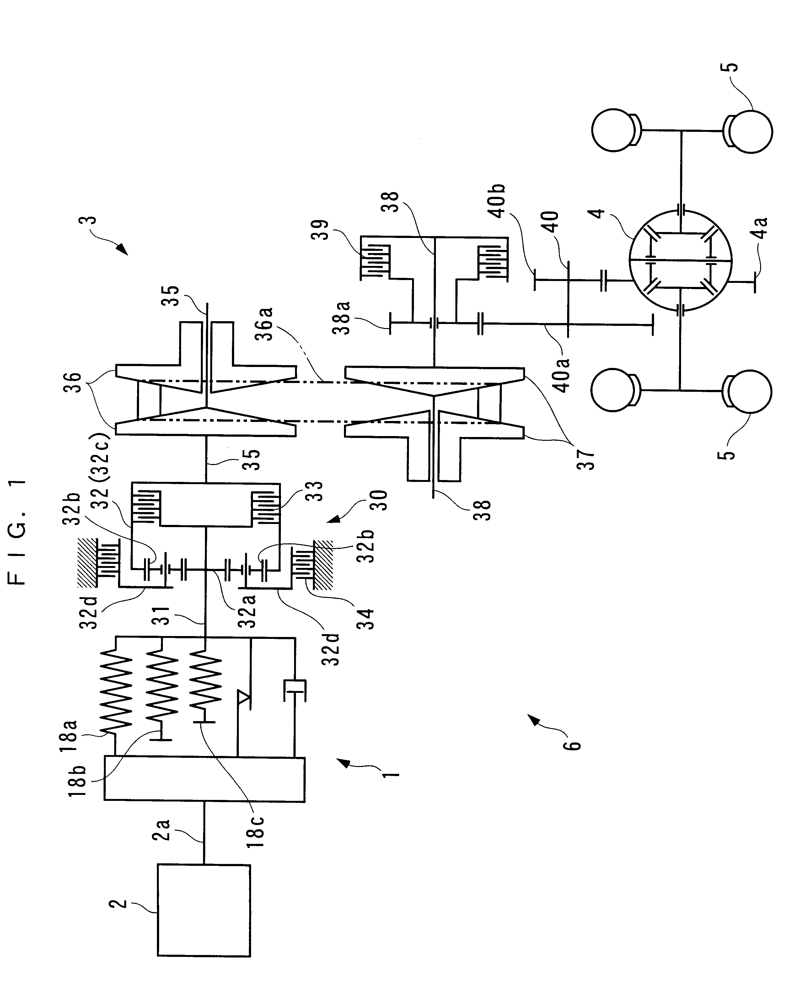
The invention will now be described in detail with reference to the drawings showing a preferred embodiment thereof. Referring first to FIG. 1, there is schematically shown the arrangement of a vehicle driving system to which is applied a flywheel device for a prime mover, according to the preferred embodiment of the present invention. As shown in the figure, in the vehicle driving system 6, an engine 2 as a prime mover is connected to driving wheels 5, 5 via the flywheel device 1, an automatic transmission 3, a differential gear mechanism 4, and the like, which enables torque from the engine 2 to be transmitted to the driving wheels 5, 5.

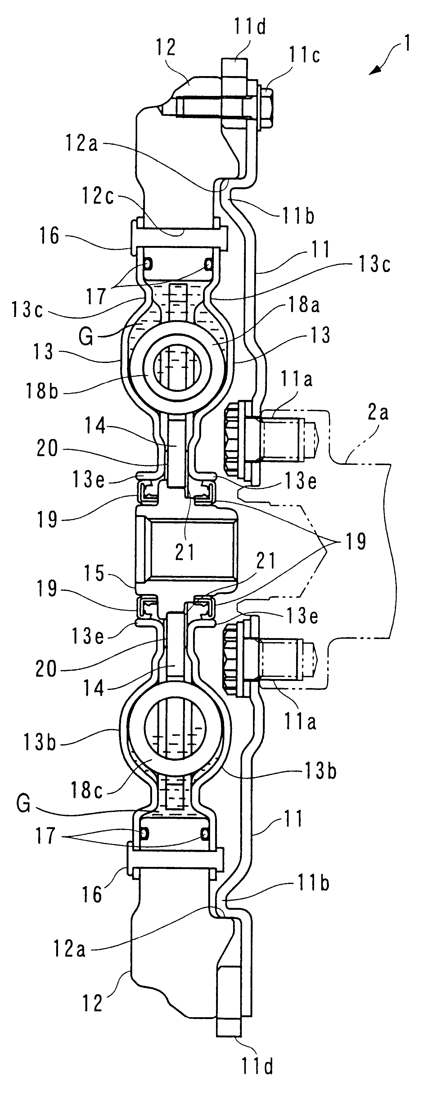
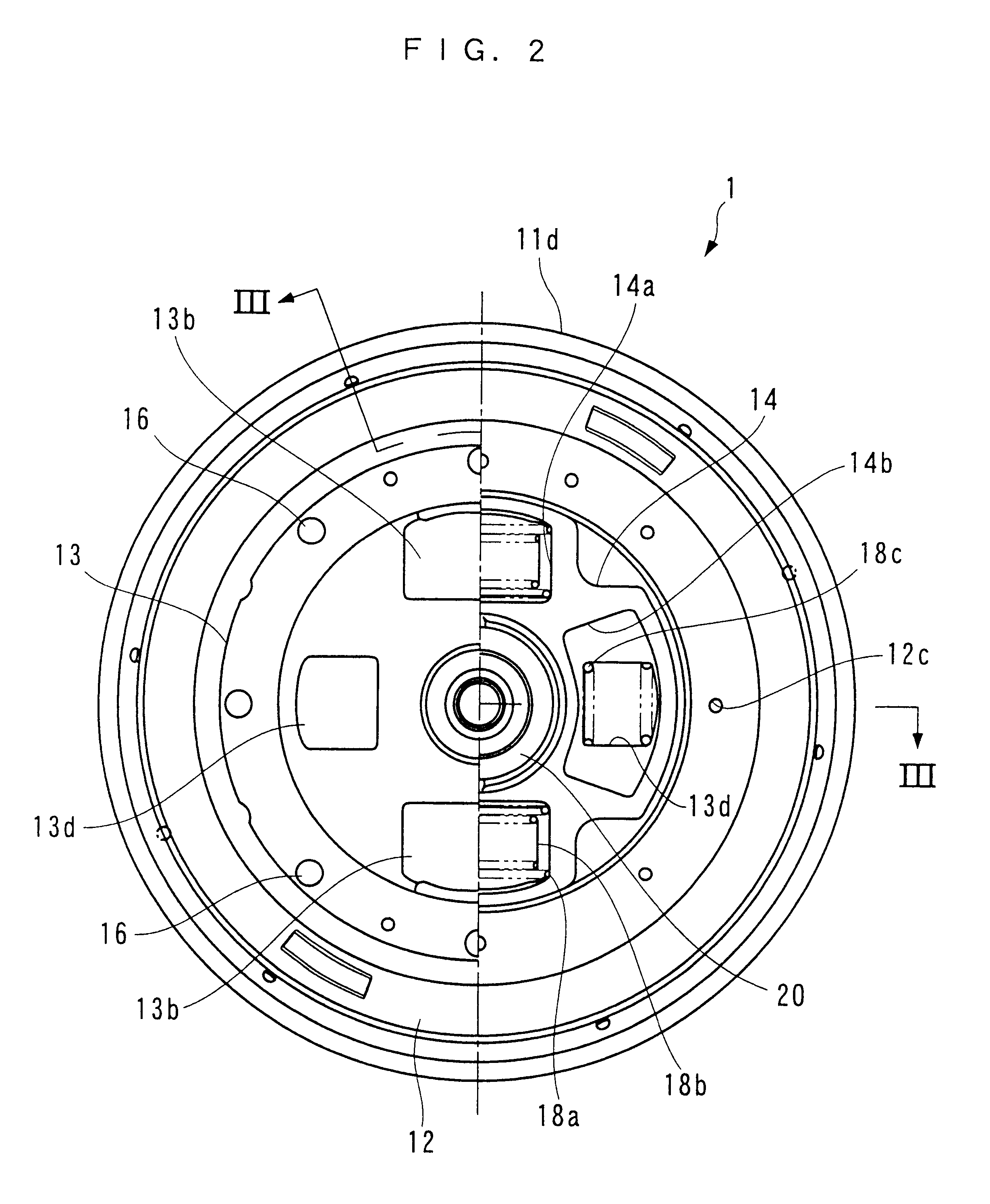
The flywheel device 1 is arranged between the engine 2 and the automatic transmission 3, and transmits torque from the engine 2 to the automatic transmission 3 while reducing engine torque variation and damping torsional vibration. As shown in FIGS. 2 and 3, the flywheel device 1 is comprised of a drive plate 11, a mass ring 12, a pair of spring ho...


PUM


Abstract

A flywheel device for a prime mover can be made compact in axial size and has an effectively increased inertial mass. The flywheel device includes a drive plate and a mass ring. The drive plate has an annular projection and is attached to a crankshaft concentric with the crankshaft. The mass ring has an annular recess and is concentrically attached to the drive plate by the annular recess being fitted on the annular projection of the drive plate. The flywheel device transmits torque from an engine as the prime mover to the input shaft of an automatic transmission while reducing variation in the torque.

Description

1. Field of the InventionThis invention relates to a flywheel device for a prime mover, such as a flywheel having a torsional vibration damper for use with a vehicle driving system, which is capable of transmitting torque from the prime mover while reducing variation in the torque and damping torsional vibration.2. Description of the Prior ArtConventionally, a flywheel device of the above-mentioned kind has been proposed e.g. by Japanese Utility Model Registration Publication (Kokoku) No. 5712273. This flywheel device is comprised of a flywheel body and a torsional vibration damper (hereinafter referred to as "the torsional damper") which are assembled into a unit. The flywheel device is arranged between the engine and the clutch. The flywheel body includes a disc-shaped base portion, and a protrusion which protrudes toward the clutch from an outer peripheral end of the base portion. The base portion has an engine crankshaft mounted in a central portion thereof, and a bearing fitted...

Claims


Application Information

Patent Timeline
Patent Type & Authority Patents(United States)
IPC IPC(8): F16F15/131F16F15/123
CPCF16F15/1315Y10T74/2125
Inventor WATANABE, NAOTOICHIJO, SHUJISUMI, MAKOTOSAOTOME, HIROSHI
Owner HONDA MOTOR CO LTD
Why Eureka
Try Eureka