Evaluation board and cable assembly evaluation method

a technology of evaluation board and assembly, which is applied in the direction of baseband system details, coupling device connections, instruments, etc., can solve the problems of poor efficiency, inability to easily perform, and the inability to evaluate equalizer circuits with accuracy only through simulations

Inactive Publication Date: 2009-07-28
FUJITSU COMPONENENT LTD
View PDF8 Cites 3 Cited by
  • Summary
  • Abstract
  • Description
  • Claims
  • Application Information

AI Technical Summary

Benefits of technology

[0010]Accordingly, it is a general object of the present invention to provide an evaluation board and a cable assembly evaluation method in which the above-described disadvantages are eliminated.
[0011]A more specific object of the present invention is to provide an evaluation board and a cable assembly evaluation method that make it possible to evaluate a cable assembly with ease and accuracy.
[0013]According to the above-described invention, it is possible to evaluate an equalizer circuit to be mounted in a cable assembly using the cable assembly without the equalizer circuit. Accordingly, it is possible to evaluate the equalizer circuit with efficiency.
[0015]According to the above-described invention, it is possible to measure the transmission characteristics of an evaluation board itself by measuring the transmission characteristics of an interconnection line pattern formed on the other side of the evaluation board. The transmission characteristics of the cable assembly can be measured with accuracy by eliminating the effect of the transmission characteristics of the evaluation board from the measurement results of the transmission characteristics of the cable assembly.
[0017]According to the above-described invention, it is possible to measure the transmission characteristics of a “double-length” interconnection line pattern including first and second interconnection line patterns. This makes it possible to measure the transmission characteristics of a cable assembly even when an evaluation or connection board is connected to each end of the cable assembly.
[0021]The above objects of the present invention are also achieved by a method of evaluating a cable assembly by connecting the cable assembly to an evaluation board, including the steps of (a) measuring a transmission characteristic of the evaluation board with an interconnection line pattern for measurement substantially equal to an interconnection line pattern of the evaluation board; (b) measuring a transmission characteristic of the cable assembly by connecting the cable assembly to the evaluation board; and (c) evaluating the transmission characteristic of the cable assembly by eliminating an effect of the measured transmission characteristic of the evaluation board from the measured transmission characteristic of the cable assembly.

Problems solved by technology

However, in the case of evaluating equalizer circuits using the conventional evaluation board, it is necessary to prepare multiple cable assemblies having respective equalizer circuits different in element constants from one another, thus resulting in poor efficiency.
Further, in the case of changing the constants, it is necessary to disassemble the plug connectors and change elements, which is not easily performable.
Further, it is impossible to evaluate equalizer circuits with accuracy only with simulations because errors occur at the time of actual mounting.

Method used


Image

  • Evaluation board and cable assembly evaluation method
  • Evaluation board and cable assembly evaluation method
  • Evaluation board and cable assembly evaluation method

Examples


first embodiment

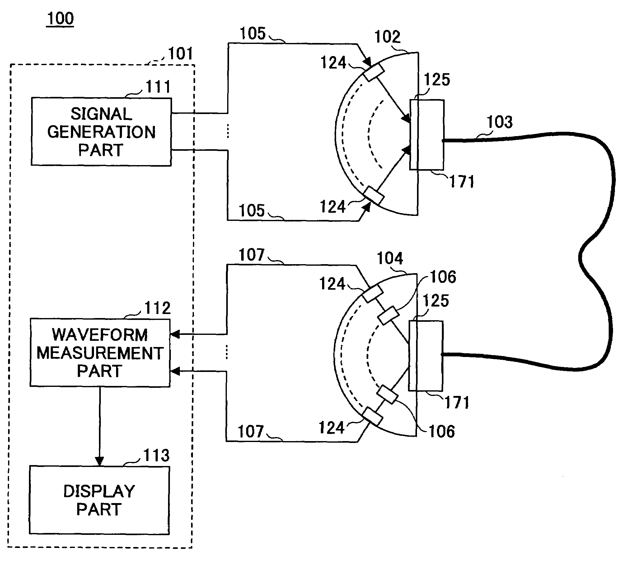
[0055]FIG. 1 is a diagram showing a system configuration according to a first embodiment of the present invention.

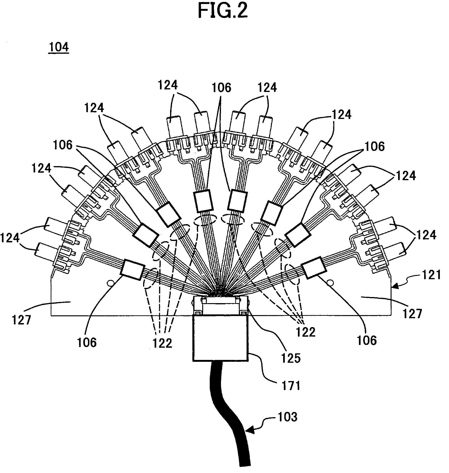
[0056]Referring to FIG. 1, an evaluation system 100 according to the first embodiment includes a measurement device 101, a connection board (a board for connection) 102, a cable assembly 103, and an evaluation board (a board for evaluation) 104.

[0057]The measurement device 101, which measures the transmission characteristics of the cable assembly 103, is formed of an oscilloscope, for instance. The measurement device 101 provides measurement signals (signals for measurement) to the cable assembly 103 through the connection board 102. The connection board 102 connects signal output cables 105 of the measurement device 101 with the cable assembly 103 through connectors. A differential transmission line pattern is formed on the connection board 102. Circuits such as an equalizer circuit are not mounted on the connection board 102. The measurement signals output from the mea...

second embodiment

[0097]FIG. 8 is a diagram showing a system configuration according to a second embodiment of the present invention. In FIG. 8, the same elements as those of FIG. 1 are referred to by the same numerals, and a description thereof is omitted.

[0098]Referring to FIG. 8, an evaluation system 400 according to the second embodiment is different from the evaluation system 100 of the first embodiment in the configuration of an evaluation board.

[0099]FIG. 9 is a plan view of an evaluation board 401 of the evaluation system 400 (shown in FIG. 8).

[0100]The evaluation board 401 includes a module socket 411 provided between the SMA socket connectors 124 and the socket connector 125. An equalizer module 412 is attached to the module socket 411. The equalizer module 412 is an electronic module integrating as many equalizer circuits 106 (shown in FIG. 1) as the number of differential transmission line pairs. The equalizer module 412 includes a printed board on which chip components are mounted, an IC...

third embodiment

[0104]FIG. 10 is a diagram showing a system configuration according to a third embodiment of the present invention. In FIG. 10, the same elements as those of FIG. 1 are referred to by the same numerals, and a description thereof is omitted.

[0105]Referring to FIG. 10, an evaluation system 500 according to the third embodiment is different from the evaluation system 100 of the first embodiment in the configuration of an evaluation board and the evaluation procedure.

[0106]FIG. 11 is a top plan view of an evaluation board 501 of the evaluation system 500. FIG. 12 is a bottom plan view of the evaluation board 501. FIG. 13 is a plan view of part of the bottom surface of the evaluation board 501. FIG. 14 is a diagram showing an interconnection line pattern on the bottom surface of the evaluation board 501. In FIGS. 11 through 14, the same elements as those of FIGS. 2 and 3 are referred to by the same numerals, and a description thereof is omitted.

[0107]On the bottom surface of the evaluati...


PUM


Abstract

An evaluation board having an interconnection line pattern formed thereon is disclosed. The interconnection line pattern has a first end to be connected to a cable assembly and a second end to be connected to a measurement device measuring the transmission characteristic of the cable assembly. The evaluation board includes an equalizer circuit equalizing the transmission characteristic of the cable assembly.

Description

BACKGROUND OF THE INVENTION[0001]1. Field of the Invention[0002]The present invention relates generally to evaluation boards and cable assembly evaluation methods, and more particularly to an evaluation board for evaluating an equalizer circuit to be mounted in a cable assembly and a cable assembly evaluation method using an evaluation board.[0003]2. Description of the Related Art[0004]In a cable assembly provided with a connector for high-speed transmission, the transmission characteristics of the cable assembly change depending on the length of a cable and the diameter of a signal line passing through the cable. In general, an equalizer circuit is mounted in the cable assembly in order to obtain good transmission characteristics.[0005]Conventionally, in order to evaluate an equalizer circuit to be mounted in the cable assembly, multiple cable assemblies having respective equalizer circuits different in element constants from one another are prepared, and their transmission charact...

Claims


Application Information

Patent Timeline
Patent Type & Authority Patents(United States)
IPC IPC(8): G01R31/02
CPCG01R31/021G01R31/58
Inventor YAMAKAMI, TOHRUKONDOU, TAKAHIRO
Owner FUJITSU COMPONENENT LTD
Why Eureka
Try Eureka