
Dual reciprocating saw

a reciprocating saw and reciprocating saw technology, applied in the direction of power driven reciprocating saws, manufacturing tools, lighting and heating apparatus, etc., can solve the problems of material damage, material cutting to move back and forth, material cutting improperly, etc., to reduce fatigue to users, reduce vibration, and improve material cutting

Inactive Publication Date: 2014-02-20
MIG7 INFUSION +1
View PDF12 Cites 9 Cited by
  • Summary
  • Abstract
  • Description
  • Claims
  • Application Information

AI Technical Summary

Benefits of technology

The present invention is a multi-blade reciprocating saw that includes two or more reciprocating blades that can move independently of each other. The blades can be simultaneously moved in opposite directions during cutting, which improves cutting performance, reduces vibration, and reduces fatigue to the user while maintaining accuracy, speed, and ease of use. The design also reduces backward / forward forces and acts as a smoother and less abrupt cut through the material.

Problems solved by technology

Although this type of cutting device is effective for many applications, there are several disadvantages to the use of such a device.
One disadvantage is that the reciprocation of the cutting blade can cause the material being cut to move back and forth due to the friction and cutting action of the cutting blade when the cutting blade moves back and forth during the cutting of the material.
Such movement of the material during the cutting process can result in improper cutting of the material and damage to the material.
Also, when the material to be cut is held in place, the reciprocating saw will tend to move back and forth during cutting thus making it difficult to hold the saw in the proper position and increasing the rate of fatigue on the user to properly hold and position the saw during cutting of a material.

Method used


Image

  • Dual reciprocating saw
  • Dual reciprocating saw
  • Dual reciprocating saw

Examples


Embodiment Construction

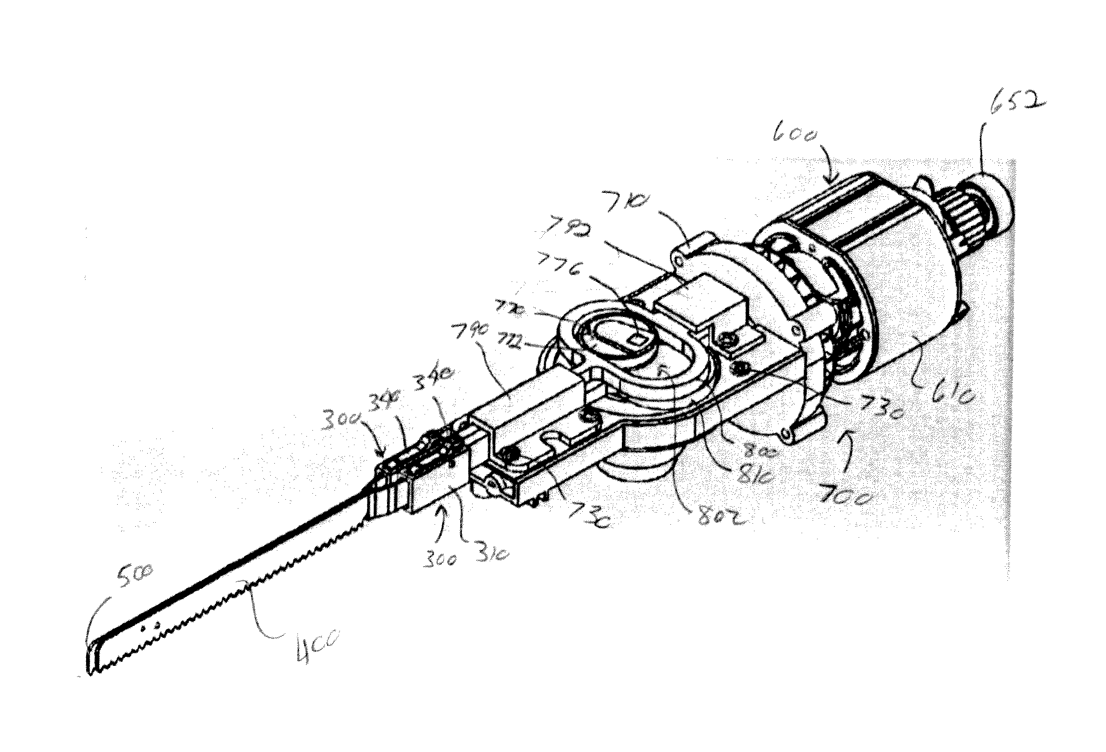
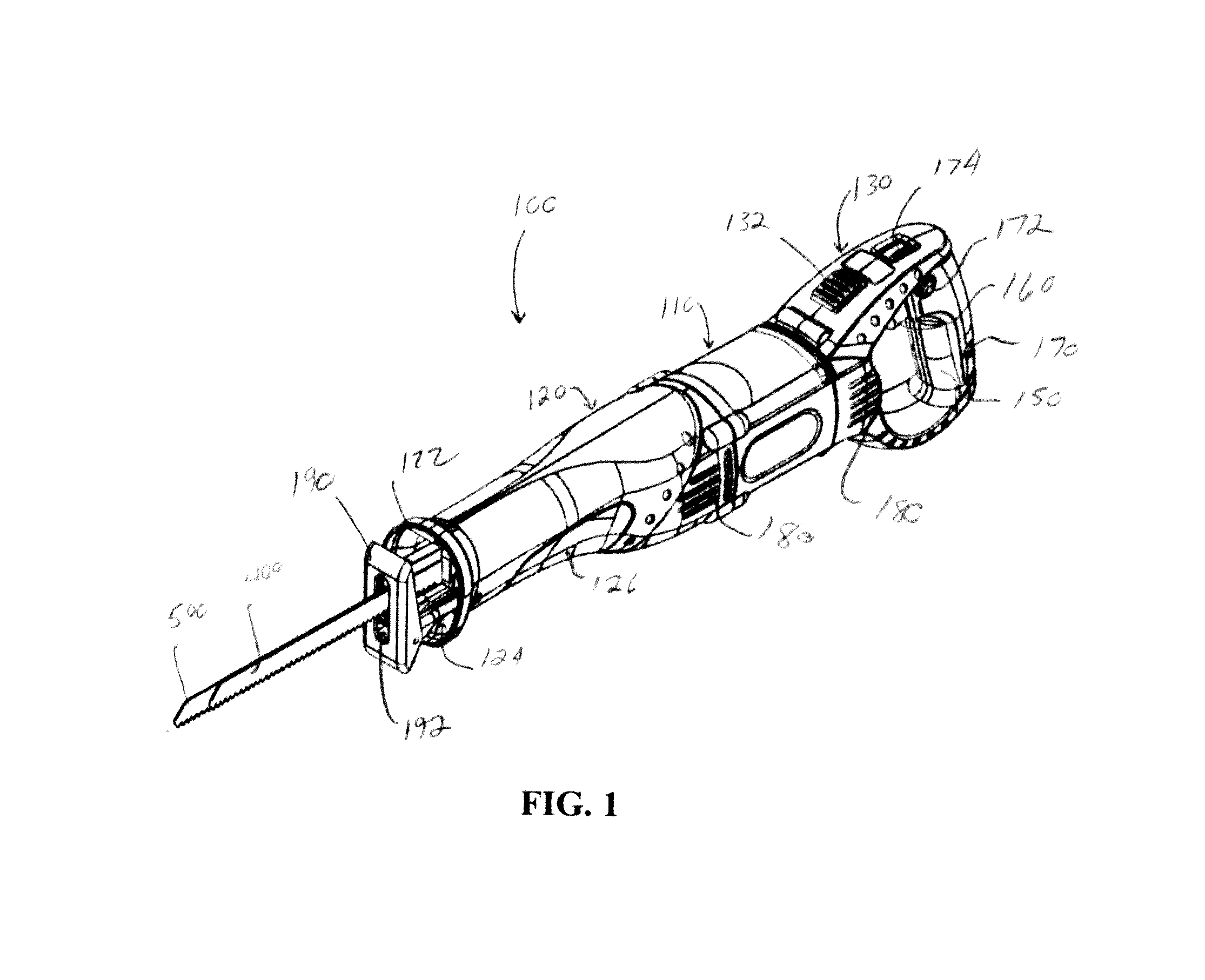
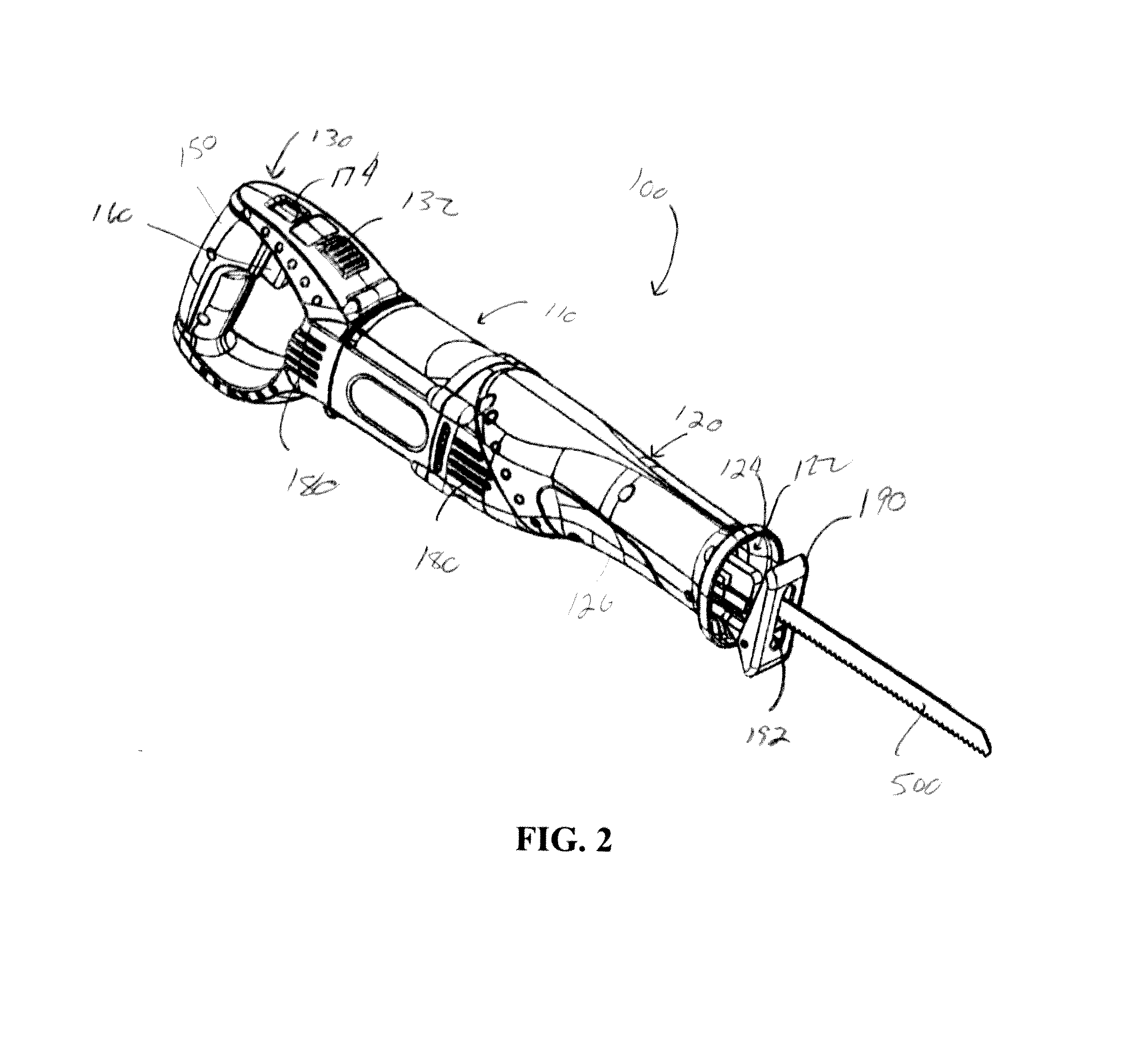
[0090]Referring now to the drawings wherein the showings are for the purpose of illustrating one non-limiting embodiment of the invention only and not for the purpose of limiting same, FIGS. 1-28 illustrate non-limiting embodiments of the reciprocating saw in accordance with the present invention.

[0091]FIGS. 1-4 illustrate one non-limiting body 110 of a reciprocating saw 100 in accordance with the present invention. FIGS. 5-7 illustrate another non-limiting body 110 of a reciprocating saw 100 in accordance with the present invention. The two bodies of the reciprocating saw are similar; however, non-limiting body of a reciprocating saw illustrated in FIGS. 5-7 has a handle 130 than can pivot and rotate relative to the main body portion 120 of the body of the reciprocating saw. The handle 130 of the body of the reciprocating saw illustrated in FIGS. 1-4 is fixed or can only rotate relative to the main body portion 120 of the body 110 of the reciprocating saw 100. The shape of the body...


PUM

PropertyMeasurementUnit
degree of rotationaaaaaaaaaa
angleaaaaaaaaaa
stroke lengthaaaaaaaaaa

Abstract

A reciprocating saw for cutting material. The reciprocating saw includes a drive system and a gear arrangement that is designed to cause first and second reciprocating saw blades to partially or fully reciprocate in opposite directions. The gear arrangement is connected or interconnected to first and second blade carrying arms. The first reciprocating saw blade is connected to the first blade carrying arm and the second reciprocating saw blade is connected to the second blade carrying arm. The gear arrangement causes the first and second blade carrying arms to move when the drive system is activated to thereby cause the first and second reciprocating saw blades to partially or fully reciprocate in opposite directions relative to one another. The gear arrangement is designed to enable a stroke length of the first and second reciprocating saw blades to be changed.

Description

[0001]The present invention claims priority on U.S. Provisional Application Ser. Nos. 61 / 449,902 filed Mar. 7, 2011; 61 / 450,196 filed Mar. 8, 2011; 61 / 450,244 filed Mar. 8, 2011; 61 / 482,463 filed May 4, 2011; 61 / 483,267 filed May 6, 2011; 61 / 529,372 filed Aug. 31, 2011; 61 / 547,092 filed Oct. 14, 2011; and 61 / 560,457 filed Nov. 16, 2011, all of which are incorporated herein by reference.[0002]The present invention is related cutting devices, particularly directed to power saws, more particularly directed to a power saw that includes a plurality of saw blades that can be moved independently of one another, and still more particularly to a power saw that includes two saw blades that can be simultaneously moved in opposite directions to one another during the cutting of material.BACKGROUND OF THE INVENTION[0003]Reciprocating saws are known in the art and used to cut many types of materials. The serrated blade cuts materials as the blade reciprocates back and forth. Most reciprocating to...

Claims


Application Information

Patent Timeline
Patent Type & Authority Applications(United States)
IPC IPC(8): B23D49/00F21V33/00B23D49/16
CPCB23D49/006F21V33/0084B23D49/16B23D51/16B23D61/121B23D61/123
Inventor VITANTONIO, MARCJACKSON, TREVORFUCHS, JR., DONALD C.SOREO, ROBERTNOTTINGHAM, JOHNSPIRK, JOHN
Owner MIG7 INFUSION
Learn More