Adapter coupler for adapting couplings of different design

a technology of adapter coupler and coupling, which is applied in the direction of valve operating means/releasing devices, couplings, transportation and packaging, etc., can solve the problems of manual process, and achieve the effect of limiting the longitudinal movement of the drawbar ey

Inactive Publication Date: 2013-12-03
VOITH PATENT GMBH
View PDF6 Cites 8 Cited by
  • Summary
  • Abstract
  • Description
  • Claims
  • Application Information

AI Technical Summary

Benefits of technology

[0020]The inventive solution is further characterized by the simple design to the height-centering mechanism such that fewer components are needed in comparison to a conventional adapter coupler (see for example the adapter coupler depicted in FIG. 1 or FIG. 2), which results in lowering the weight of the adapter coupler.
[0023]For example, to form the tension yoke, one realization of the inventive solution provides for the second connecting mechanism to comprise two preferably parallel supports with a horizontally-aligned tension bolt connecting said supports, wherein the drawhook of the second coupling can be received in the area between these two parallel supports. In this realization, the drawbar eye should preferably be provided on the upper side of the coupler support and at least partly align substantially axially with the area between the two supports. This facilitates the manipulating of the adapter coupler since the adapter coupler is usually inserted into the drawhook of a coupling to be adapted from above. Of course, other realizations are also conceivable.
[0025]In an advantageous development of the latter embodiment, the mechanism used to move the draw-bar eye in the longitudinal direction of the adapter coupler relative to the tension yoke comprises a first as well as a second limit stop so as to be able to limit the longitudinal movement of the drawbar eye. This thus ensures that the adapter coupler is only pivotable relative the drawhook within a pre-definable vertical angular range. The first and second limit stop are thereby to be configured in such a way that the allowable pivoting range can be selected so as to allow dynamic vehicle movements during vehicle operation.
[0026]In one preferred development of the latter embodiment, the mechanism by means of which the drawbar eye is connected to the coupler support of the adapter coupler comprises at least one spring element to pretension the drawbar eye in the direction of the second connecting mechanism. The amount of pretensioning exerted by the spring element is thereby preferably predefinable. The providing of at least one spring element enables the cushioning of the dynamic vehicle movements occurring during vehicle operation.
[0028]It is particularly preferred for the support to be releasably connected to the coupler housing, thereby enabling e.g. the retrofitting of an adapter coupler with a height-centering mechanism.

Problems solved by technology

However, the manual process to do so, and in particular the manual inserting of the adapter coupler 101 into the interface between the couplings to be adapted, for example into the drawhook 50 of a screw-type coupling, is difficult since it is not possible for a user to hold the weight of the adapter coupler 101 on the one hand and properly position the height-centering mechanism at the drawhook 50 on the other.

Method used


Image

  • Adapter coupler for adapting couplings of different design
  • Adapter coupler for adapting couplings of different design
  • Adapter coupler for adapting couplings of different design

Examples


Embodiment Construction

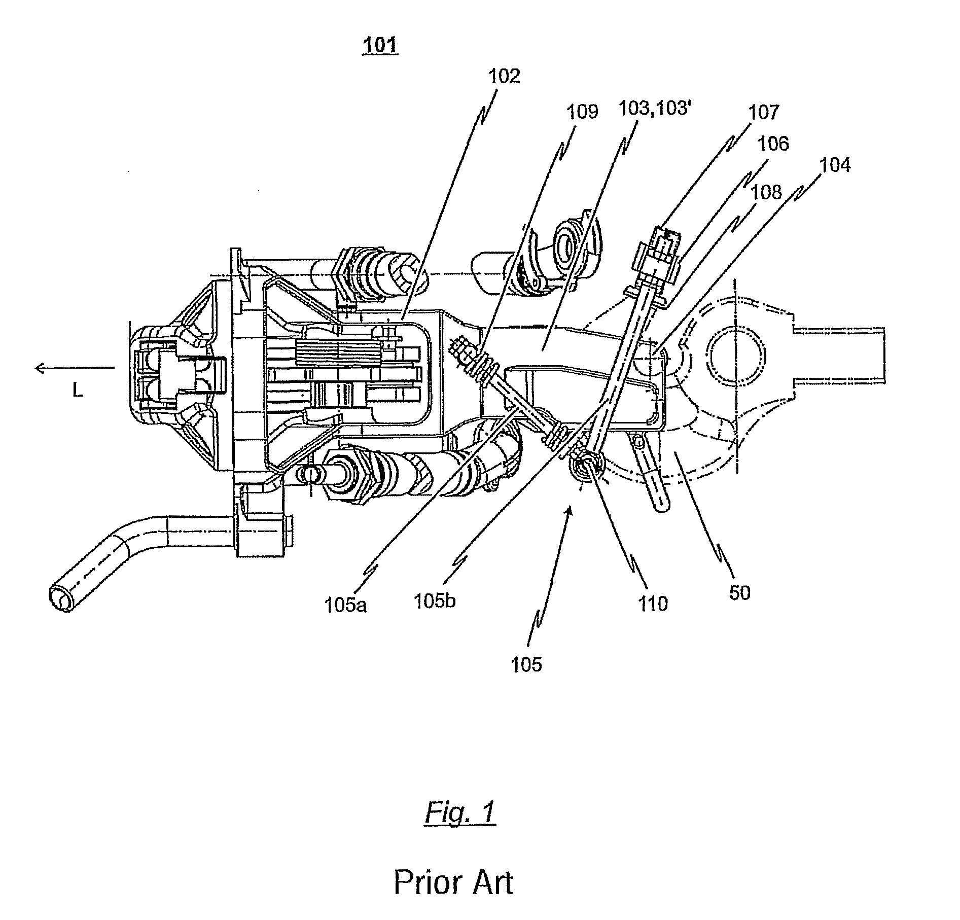
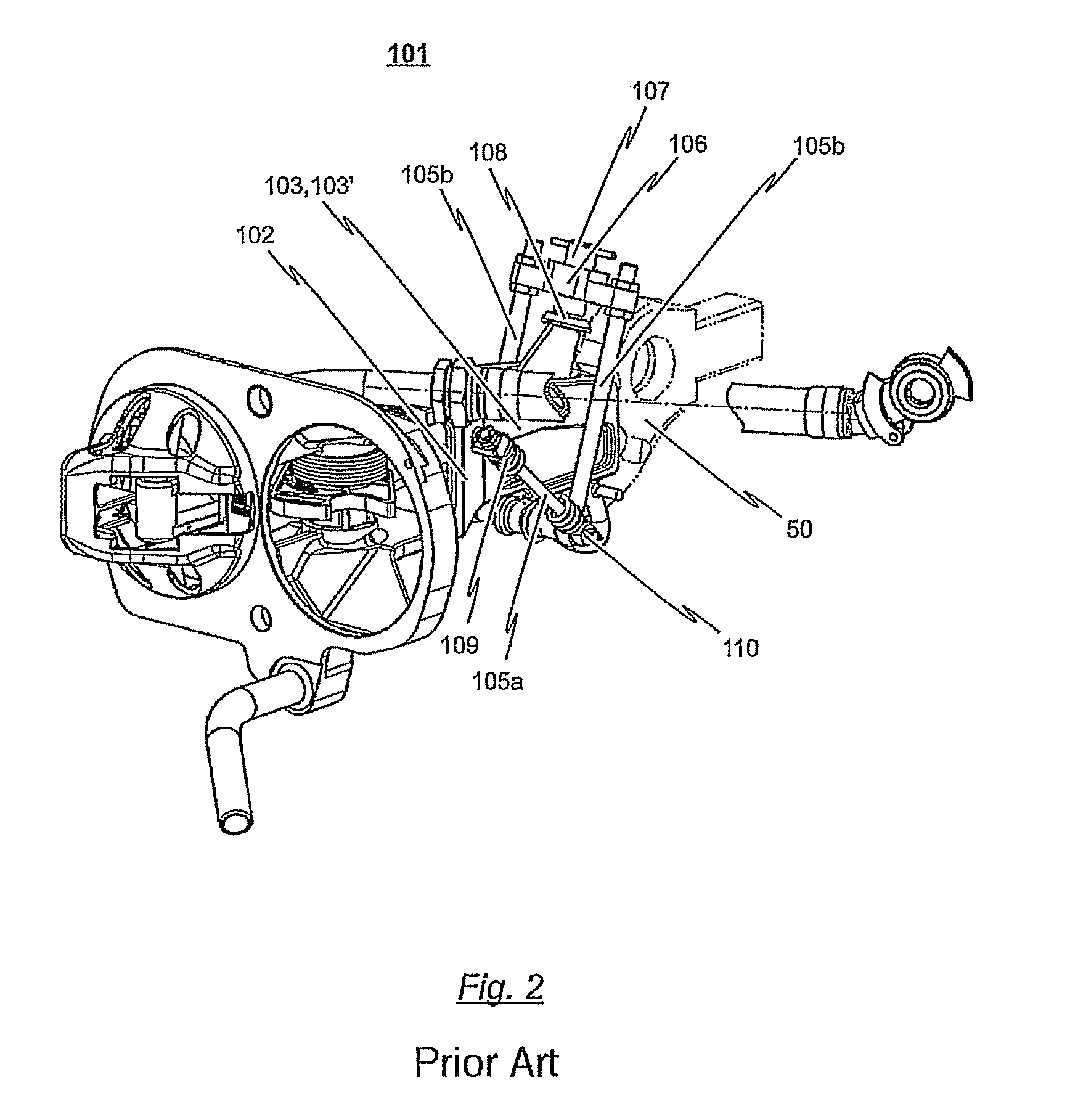
[0040]FIGS. 1 and 2 show an adapter coupler 101 as known from the prior art which comprises a bell-crank lever 105 fastened to the lug of a drawhook 50 by means of a yoke 107 for height centering purposes. The bell-crank lever 105 is thereby affixed to the side of the housing 102 of the adapter coupler 101 and ensures the height centering of the adapter coupler 101.

[0041]As noted above, a disadvantage to the conventional adapter coupler 101 depicted in FIGS. 1 and 2 is that it is relatively difficult to mount the adapter coupler 101 on the drawhook 50 of a coupling to be adapted due to the relatively complicated structure of the height-centering mechanism in the form of a bell-crank lever 105. It is in particular not possible for one person to mount the adapter coupler 101 on the drawhook 50 of a coupling to be adapted by themselves, since one person alone cannot hold the adapter coupler 101 and properly position the height-centering mechanism on the drawhook 50 all at the same time...


PUM


Abstract

An adapter coupler (1) for adapting couplings of different design, wherein the adapter coupler (1) comprises a first connecting mechanism for releasably connecting the adapter coupler (1) to a first coupling, a second connecting mechanism for releasably connecting the adapter coupler (1) to the drawhook (50) of a second coupling, and a coupler housing (2) for connecting the first connecting mechanism to the second connecting mechanism, and wherein the second connecting mechanism comprises a tension yoke (8) with which to engage with the drawhook (50) of the second coupling. The adapter coupler (1) having a mechanism for height centering, comprising a drawbar eye (14) connected to the coupler housing (2), wherein the drawbar eye (14) is arranged and configured relative the tension yoke (8) such that upon the adapter coupler (1) being inserted into the jaw of the drawhook (50) of the second coupling, the drawhook (50) can engage in one joint process with both the accommodation formed by the tension yoke (8) as well as with the drawbar eye (14).

Description

BACKGROUND OF THE INVENTION[0001]1. Field of the Invention[0002]The invention relates, in general, to an adapter coupler and in particular to an adapter coupler for adapting couplings of different design.[0003]2. Background Information[0004]The adapter coupler of interest comprises a first connecting mechanism for the releasable connecting of the adapter coupler to a first coupling, a second connecting mechanism for the releasable connecting of the adapter coupler to the drawhook of a second coupling, as well as a coupler support to connect the first connecting mechanism to the second connecting mechanism, wherein the second connecting mechanism comprises a tension yoke, with the tension yoke having a first and a second support connectable to a tension bolt such that an accommodation is formed to receive the drawhook of the second coupling.[0005]The adapter coupler of interest may connect different couplings between an automatic central buffer coupling and a screw-type coupling, whe...

Claims


Application Information

Patent Timeline
Patent Type & Authority Patents(United States)
IPC IPC(8): B61G1/00
CPCB61G5/04
Inventor KOBERT, SIEGFRIEDKOLSHORN, KAY UWEBEHRENS, DIRK
Owner VOITH PATENT GMBH
Why Eureka
Try Eureka