
Cartridge system with rotatable closure and dispensing tube

a cartridge system and rotatable technology, applied in the direction of liquid/fluent solid measurement, liquid dispensing, containers, etc., can solve the problems of perforation, user needs to perform rotational motion, and may evaporate paste ingredients, etc., to reduce or overcome shortcomings, safe closure of cartridges, and simple

Active Publication Date: 2013-12-03
HERAEUS MEDICAL
View PDF147 Cites 10 Cited by
  • Summary
  • Abstract
  • Description
  • Claims
  • Application Information

AI Technical Summary

Benefits of technology

The system simplifies the operation of cartridge systems, reduces the risk of user errors, prevents contamination, and maintains the integrity of volatile components by allowing rapid and secure opening and closing of cartridges, ensuring consistent mixing ratios and efficient application of medical cements.

Problems solved by technology

This is disadvantageous in that the user needs to perform rotational motions twice until the paste material can be expelled.
In the interim between the cartridges being opened and the dispensing tube being inserted, ingredients of the pastes may evaporate, especially if the pastes contain volatile substances.
It is disadvantageous that the perforation might be associated with particles detaching from the wall and then entering the pasty material.
Thus far, no suitable cartridge systems have been proposed for said cements.
In this context, it is disadvantageous that packaging pasty materials in tubular bags and, in addition, in cartridges is quite expensive and reserved for special applications only.
Moreover, it is a problem in many applications, especially in the field of medicine, that parts of the cut tubular bags may become detached and thus may enter into the pasty components and thus contaminate the mixing ware.
This is disadvantageous in that the closure not only is plugged into the openings, but also snapped-in in the bracket such that removing the closure requires an effort to be made.
Moreover, removed from the cartridge system, the closure may get in the way or, in case it is to be used to re-close the openings, it may get lost.

Method used


Image

  • Cartridge system with rotatable closure and dispensing tube
  • Cartridge system with rotatable closure and dispensing tube
  • Cartridge system with rotatable closure and dispensing tube

Examples


Embodiment Construction

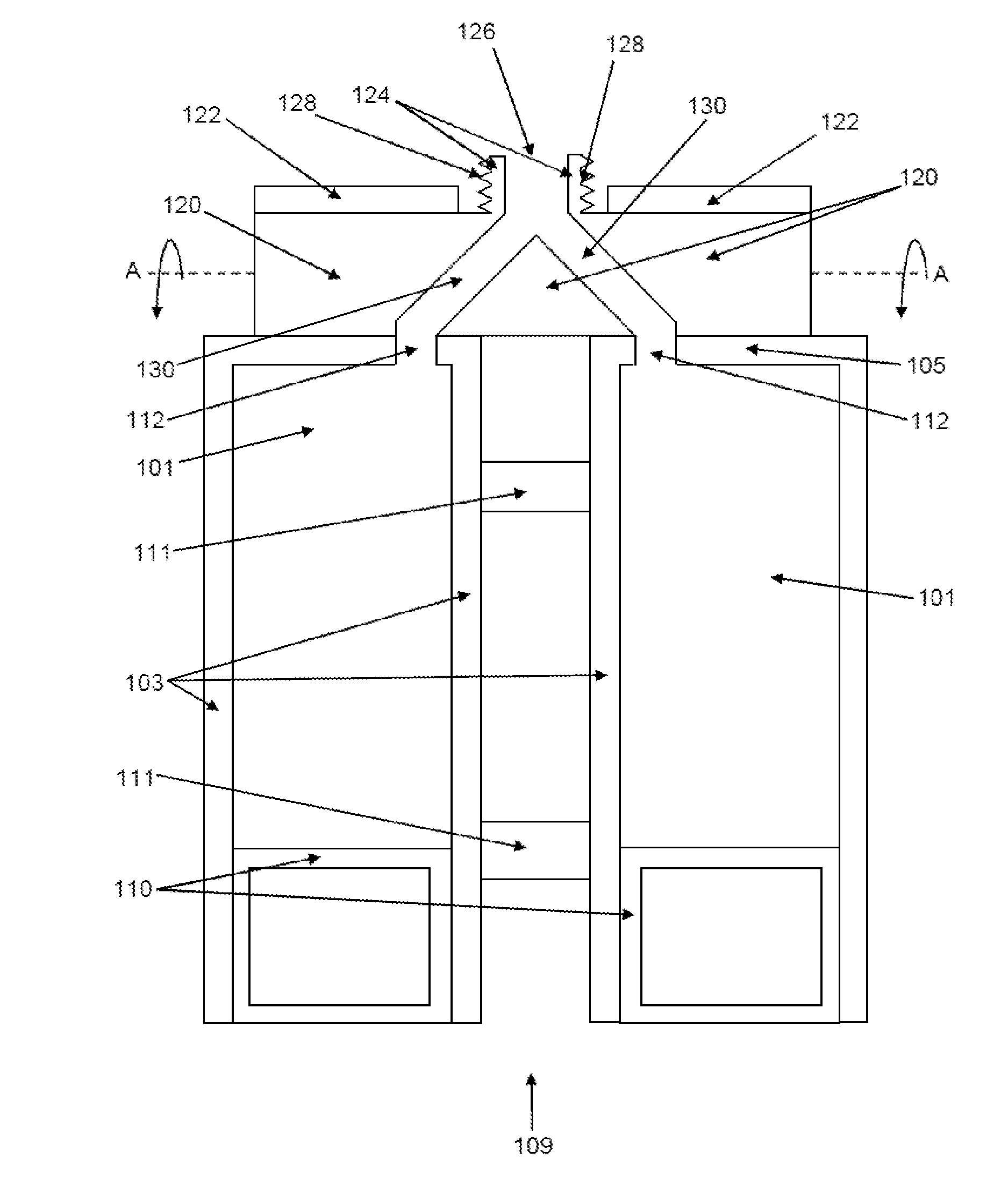
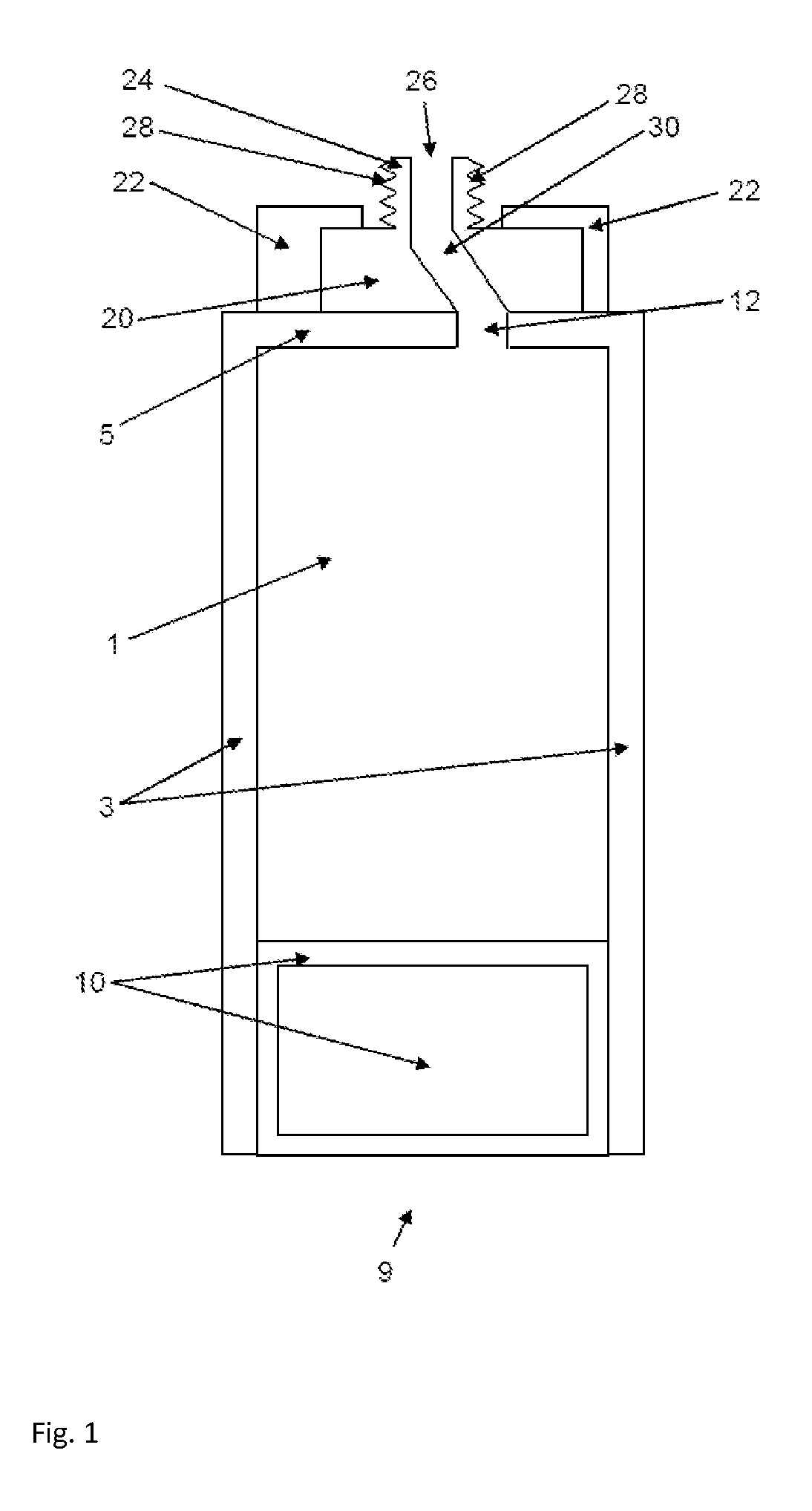
[0046]The schematic cross-sectional view shown in FIG. 1 shows a cartridge (1) that is bounded on all sides by cartridge walls (3), on the front side by a cartridge head (5), and from the direction of the cartridge floor (9) by a feed plunger (10). An opening (12) is provided in the wall forming the cartridge head (5), whereby a flowable material (not shown) contained in the cartridge (1) can be expelled through said opening through insertion of the feed plungers (10).

[0047]A cylindrical valve (20) is arranged on the cartridge head (5) in a bracket (22) and mounted in the bracket (22) such as to be rotatable about its axis of symmetry. The cartridge head (5) comprises a depression (not shown) shaped like a cylinder jacket section such that the cylindrical valve (20) fits exactly into the depression. The opening (12) is not situated in said depression. The cylindrical valve (20) comprises on one side of its cylinder jacket surface a hollow, cylindrical connector (24) having an outlet...


PUM


Abstract

Cartridge systems for application of a material have at least one cartridge having cartridge walls, a cartridge head having at least one opening in the cartridge head, and a bracket arranged on the cartridge head. A valve is mounted in rotatable manner in the bracket and has at least one passage through the valve that is connected to an outlet opening of the valve. In a closed position, the valve closes the at least one opening of at least one cartridge in a sealed manner. The at least one passage of the valve is connected to the at least one opening when the valve is located in an open position such that the cartridge content is squeezable out of the at least one cartridge through the outlet opening, and further wherein the valve is configured to be transitioned from a closed position to an open position through a rotation of the valve about an axis of symmetry of the valve.

Description

[0001]The invention relates to a cartridge system for application of a material, in particular a medical cement, comprising at least one cartridge, whereby the at least one cartridge comprises cartridge walls and one cartridge head each having at least one opening in each cartridge head, and a bracket is arranged on the cartridge head or cartridge heads.BACKGROUND OF THE INVENTION[0002]Reactive pasty two- or multi-component systems must be stored separately after their production and until their application in order to prevent premature, inadvertent reactions of the components. Cartridge systems for the application of pasty two- or multi-component systems have been known for decades. The following documents are cited for exemplary purposes, CH 669 164 A5, EP 0 607 102 A1, EP 0 236 129 A2, DE 3 440 893 A1, U.S. Pat. No. 4,690,306 A, US 2009 / 062808 A1, EP 0 787 535 A1, WO 2006 / 005 206 A1, EP 0 693 437 A1, EP 0 294 672 A, EP 0 261 466 A1, and EP 2 008 707 A1. After the cartridges are f...

Claims


Application Information

Patent Timeline
Patent Type & Authority Patents(United States)
IPC IPC(8): B67D7/70B65D88/54B65D35/54G01F11/00B67D7/06B65D47/20A61C5/04B67D7/78B67D3/00
CPCA61B17/8833B05C17/00516B05C17/00553B05C17/01B65D81/325B05C11/1031
Inventor VOGT, SEBASTIANBUCHNER, HUBERTSCHNIEBER, TIM
Owner HERAEUS MEDICAL
Learn More