Display device

a technology for locating a closed base and a device, which is applied in the field of display devices, can solve the problems of occupying a disproportionate amount of floor space, difficult construction, and disproportionately expensive floor space for such devices, and achieves the effect of reducing construction costs and reducing construction costs

Active Publication Date: 2013-12-03
DEVITO JOHN P
View PDF13 Cites 10 Cited by
  • Summary
  • Abstract
  • Description
  • Claims
  • Application Information

AI Technical Summary

Problems solved by technology

Still further, such devices typically require a power source for operation.
Unfortunately, in many retail stores, for example, such power is not readily available and, even if it is available, locating a closed base as required for such devices is not only relatively expensive, but can also be difficult to build, can take up a disproportionate amount of floor space, and can hinder changing the layout of the store and its shelves should a change be desired later.
Thus, such high security displays are not readily susceptible to use in many open displays, such as peg-boards, which are commonly and easily spread throughout retail facilities at locations where electrical power is not always readily available.
In any event, while expensive articles may benefit greatly from relatively expensive security devices having electronic alarms, in many instances the cost associated with protecting the article against theft is not justified relative to the cost of the displayed article itself.
Unfortunately, many display devices intended for use with low end present their own difficulties.
For example, in order to be securely mounted to a wall, some require damaging the wall, and also require the use of special hardware.
Further, with some displays, different versions are required to display different articles, and custom designs can increase the cost of the devices as well as making maintenance of adequate inventories of the display devices more costly as well.
Still further, the manner of presentation of the articles is sometimes undesirable by, for example, failing to present the articles in an attention catching manner.
Additionally, the life of some display devices is affected by their tendency to fray recoil cables.

Method used


Image

  • Display device
  • Display device
  • Display device

Examples


Embodiment Construction

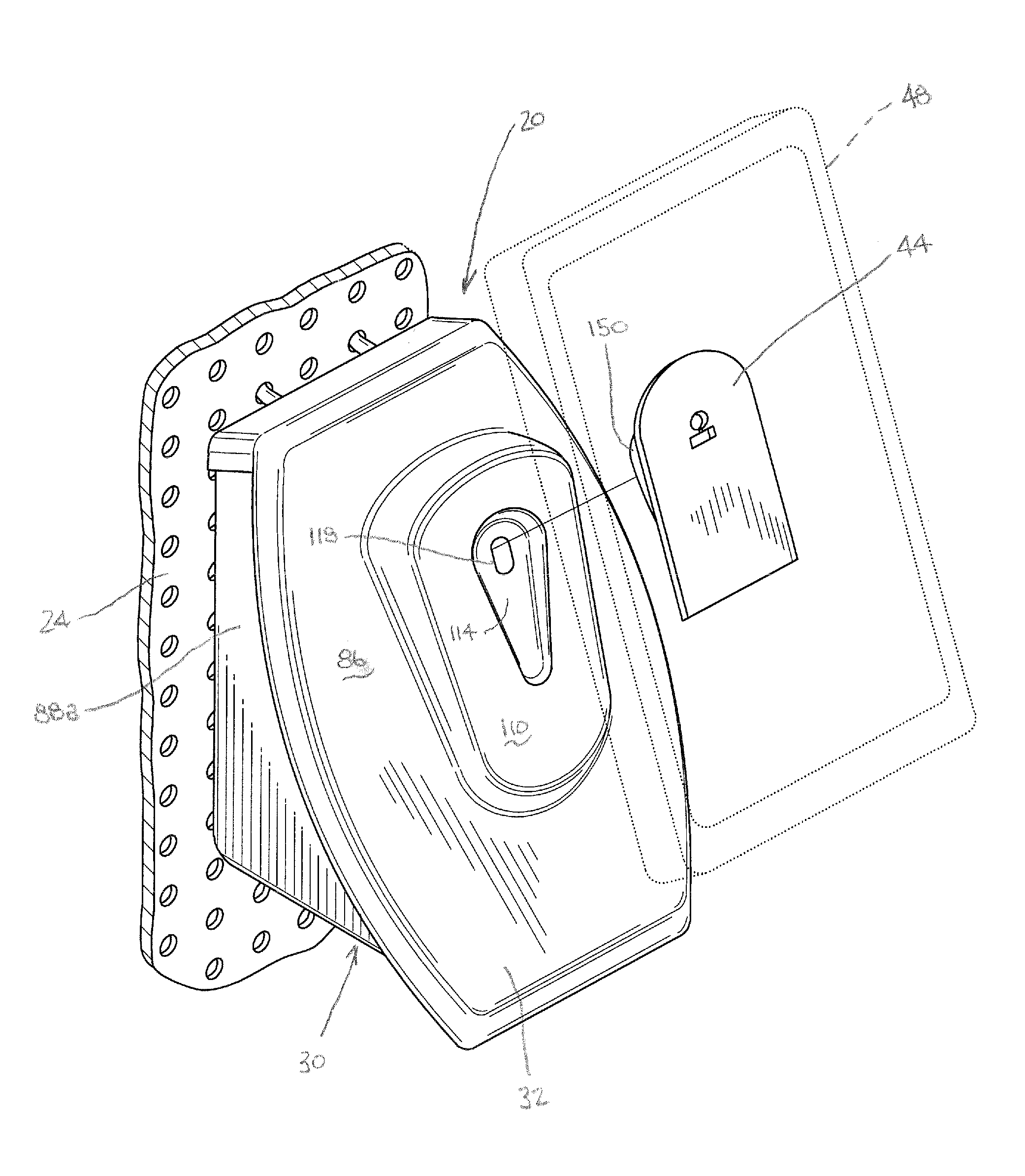
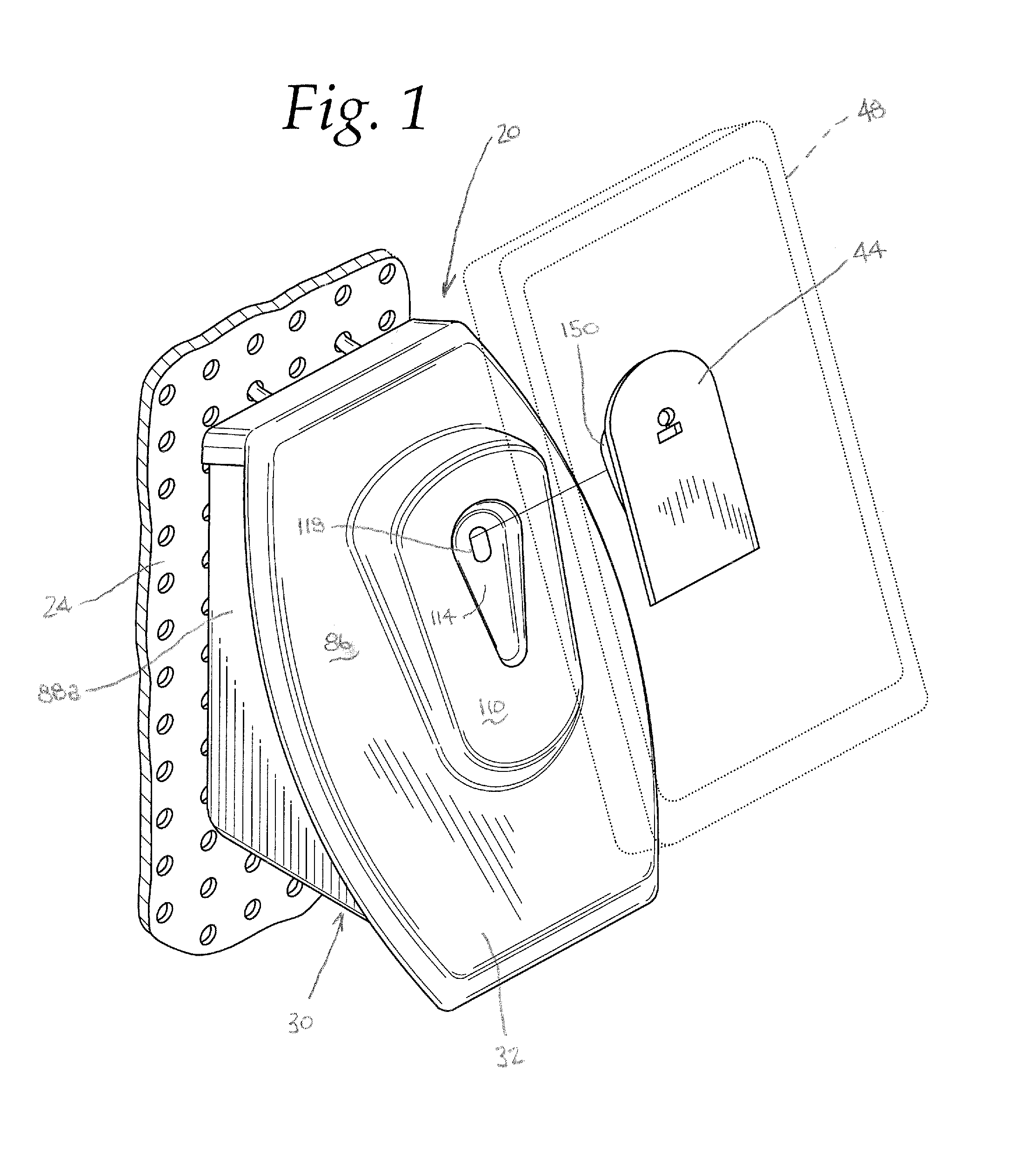
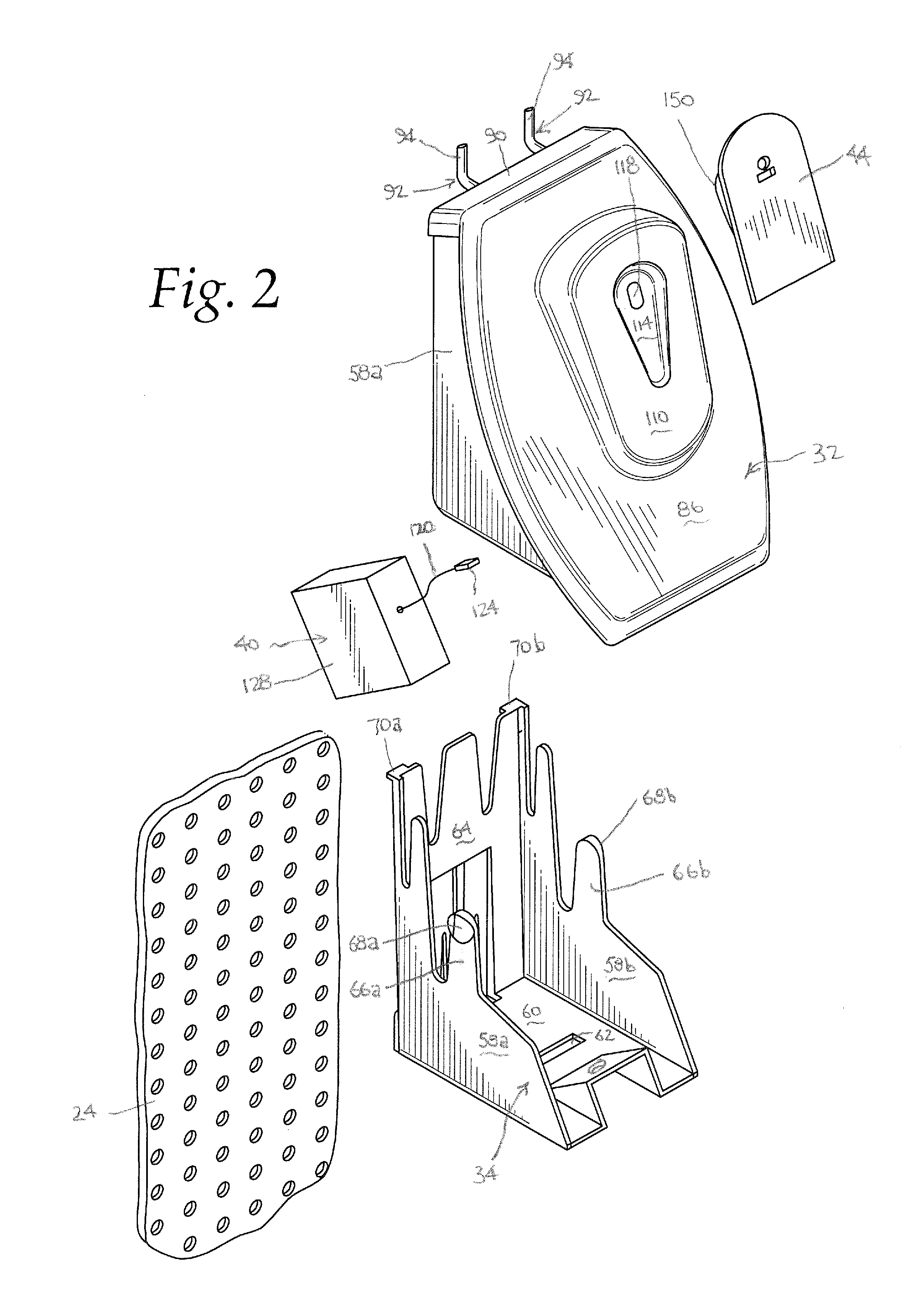
[0036]A display device 20 according to the present invention is shown in FIG. 1, mounted to a peg-board 24. As best illustrated in FIG. 2, the device 20 generally consists of a base housing 30 (consisting of an upper or front base housing portion 32 and a lower or rear base housing portion 34), a recoil mechanism 40, and an adapter plate 44, and is advantageously suited for displaying an article 48 (in phantom in FIG. 1) to gain the attention of potential purchasers as well as to allow such potential purchasers to handle the article 48. The front and rear base housing portions 32, 34, which may be advantageously molded from poly-carbonate (a recyclable plastic), together define a substantially enclosed space adjacent the front face of the peg-board 24.

[0037]It should be understood that references herein to “peg-boards” are intended to include not only peg-boards such as are known in the industry, but include any surface having holes therethrough for mounting thereon. Thus, peg-board...


PUM


Abstract

A device for displaying an article on a peg-board, including first and second housing portions securable to the front face of the peg-board, a recoil mechanism for a cable, and an adapter plate secured to the cable distal end and securable to an article to be displayed. The housing first portion has L-shaped prongs at its top with a distal end extending upwardly adjacent the peg-board back. The housing second portion has L-shaped prongs at its bottom with a distal end extending downwardly adjacent the peg-board back. The housing portions define a substantially enclosed space adjacent the peg-board front face, and the housing first portion defines a housing front face with an opening through the housing front face to the enclosed space. The recoil mechanism is biased toward retracting the cable into the recoil mechanism and disposed in the base housing enclosed space with the cable extending through the housing front face opening with the cable distal end outside the housing enclosed space.

Description

CROSS-REFERENCE TO RELATED APPLICATIONS[0001]This is a non-provisional patent application claiming priority to U.S. Provisional Application Ser. No. 61 / 367,681, filed Jul. 26, 2010, entitled “Phone Pod”. The entirety of the disclosure of Ser. No. 61 / 367,681 is hereby fully incorporated by reference.FEDERALLY SPONSORED RESEARCH OR DEVELOPMENT[0002]Not Applicable.MICROFICHE / COPYRIGHT REFERENCE[0003]Not Applicable.FIELD OF THE INVENTION[0004]The present invention relates to displays, and more particularly to displays which allow the displayed articles to be seen and handled by interested users.BACKGROUND OF THE INVENTION[0005]Display of articles intended for sale, for example, in retail stores, are of course well known.[0006]In some instances, it is desirable for the articles to not only be visibly displayed, but also displayed in a manner which will allow a user to pick up and handle the article. For example, cellular phones, computer mouses, handheld calculators, etc. are frequently ...

Claims


Application Information

Patent Timeline
Patent Type & Authority Patents(United States)
IPC IPC(8): A47B96/06A47K1/00E04G3/00E04G5/06F21V21/00F21V35/00A47G29/00A47F7/00A47F5/08
CPCA47F5/0807F16M11/041
Inventor DEVITO, JOHN P.
Owner DEVITO JOHN P
Why Eureka
Try Eureka