Optical sensor including disposable and reusable elements

a technology of optical sensors and reusable elements, applied in the field of non-invasive optical sensors, can solve the problems of reducing the chance of a resurgence, reducing the efficiency of resuscitation, and reducing the cost of disposable sensors, so as to reduce the chance, reduce the chance, and reduce the effect of resuscitation

Active Publication Date: 2013-12-03
CERCACOR LAB INC
View PDF297 Cites 467 Cited by
  • Summary
  • Abstract
  • Description
  • Claims
  • Application Information

AI Technical Summary

Benefits of technology

[0011]Accordingly, one aspect of an embodiment of the present disclosure is to provide a sensor having reusable and disposable components. In an embodiment, the sensor advantageously includes a disposable component structured to provide a locking feature capable of reducing a chance that the disposable and reusable components can separate when attached or otherwise in close proximity to the body. In an embodiment, a locking mechanism takes advantage of longitudinal displacement to engage when the reusable and disposable portions of the sensor are curved around the measurement site (such as a finger). Separation of the reusable portion from the disposable portion is then advantageously complicated until the sensor is removed from the patient and the displacement is reversed.
[0012]A further aspect of an embodiment of this disclosure is that the a portion of the reusable sensor component, such as, for example, the front portion or casing of the reusable sensor component can be attached to and released from a corresponding front housing component on the disposable component substantially vertically, substantially horizontally, or angularly. As such, for example, the front casing of the reusable sensor can attach to and release from the disposable component via the underside of the front casing (e.g., due to upward pulling by the patient or medical personnel), the front of the casing (e.g., due to lateral pulling) or angularly through a portion of both the underside and the front of the casing. This configuration allows for efficient, straightforward mating and separation of the reusable and disposable sensor components. Moreover, strain on the connection between the front portion of the reusable sensor component and the front housing of the disposable component, such as strain due to pulling by the patient or medical personnel, is also advantageously reduced.

Problems solved by technology

However, reusable sensors are often available in a limited number of sizes even though patient measurement sites, such as fingers or toes, can have a much larger size distribution.
Therefore, sometimes reusable sensors do not readily conform to each patient's attachment site.
However, disposable sensors are generally more costly due to limited use of the relatively expensive sensor components which could otherwise last for repeated uses.
While this design reuses some of the expensive electronic components, others are still discarded.
In this design, the electronics are reusable; however, the multiple wires tend to be somewhat difficult to properly attach, especially with a moving patient.
Separation of such disposable tape sandwiches can be cumbersome.

Method used


Image

  • Optical sensor including disposable and reusable elements
  • Optical sensor including disposable and reusable elements
  • Optical sensor including disposable and reusable elements

Examples


Embodiment Construction

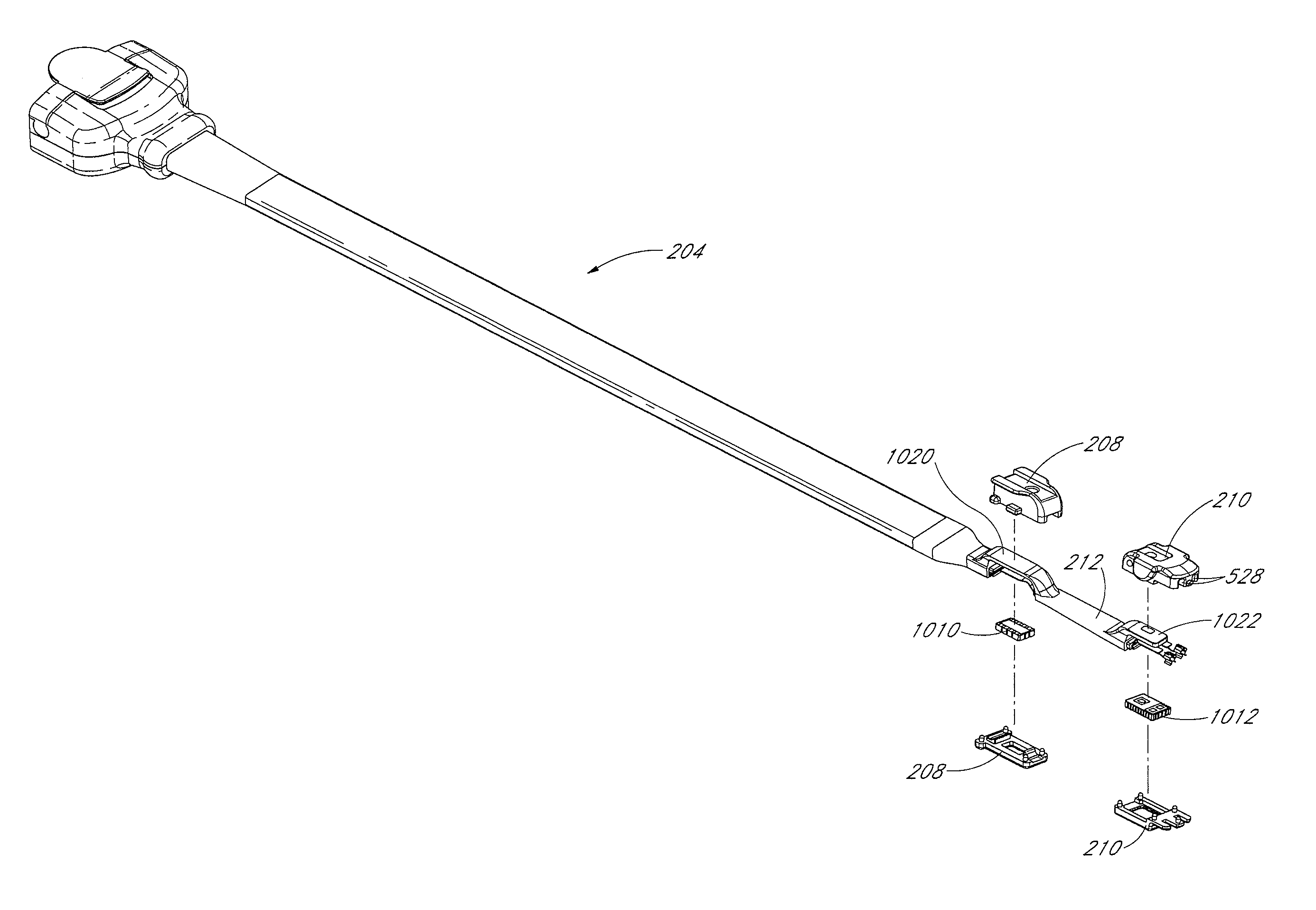
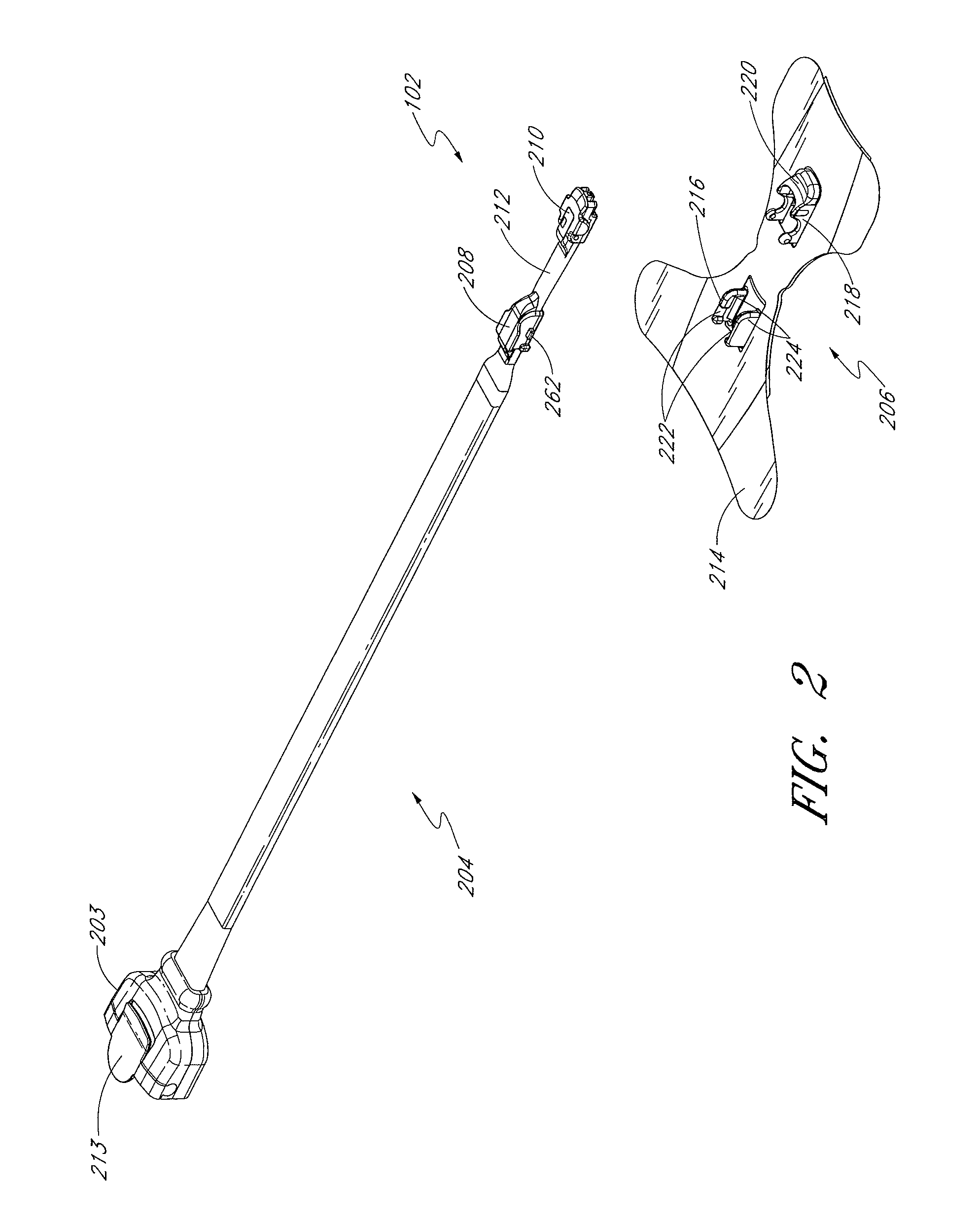
[0031]An embodiment of the present disclosure is a sensor with a reusable component and a disposable component. The reusable component generally includes reusable relatively expensive electronic components of a sensor, including, for example, the emitters and detector(s). In an embodiment, the emitters and the detector(s) are located in respective casings connected by a short flexible circuit. In an embodiment, a disposable component includes mechanically matable portions adapted to mechanically mate with the casings of the reusable component. In an embodiment, the casings of the reusable component mate with the disposable component in a manner that provides an assembly / disassembly state, and an attached state. During the assembly / disassembly state, a caregiver can readily and straightforwardly assemble the sensor by aligning the casings on the reusable component and the mechanical housings of the disposable component and snapping or sliding them together. In an embodiment, the forw...


PUM

PropertyMeasurementUnit
thickaaaaaaaaaa
thickaaaaaaaaaa
thickaaaaaaaaaa

Abstract

An embodiment of the present disclosure provides a noninvasive optical sensor or probe including disposable and reusable components. The assembly of the disposable and reusable components is straightforward, along with the disassembly thereof. During application to a measurement site, the assembled sensor is advantageously secured together while the componentry is advantageously properly positioned.

Description

CROSS-REFERENCE TO RELATED APPLICATIONS[0001]This application claims priority benefit under 35 U.S.C. §119(e) to U.S. Provisional Patent Application Ser. No. 61 / 222,450, filed Jul. 1, 2009 and is a continuation-in-part of U.S. application Ser. No. 11 / 606,455, filed Nov. 29, 2006, published as U.S. Patent Application Publication No. 2007 / 0123763. The disclosures of each of the priority applications are incorporated by reference herein. Additionally, this application relates to U.S. Pat. No. 6,920,345, issued Jul. 19, 2005, U.S. Pat. No. 7,225,007, issued May 29, 2007, U.S. application Ser. No. 11 / 754,972, filed May 29, 2007, published as U.S. Patent Application Publication No. 2007 / 0244378, and U.S. application Ser. No. 11 / 606,455, filed Nov. 29, 2006, published as U.S. Patent Application Publication No. 2007 / 0123763, the disclosures of which are incorporated in their entirety by reference herein.FIELD OF THE DISCLOSURE[0002]The present disclosure relates to noninvasive optical senso...

Claims


Application Information

Patent Timeline
Patent Type & Authority Patents(United States)
IPC IPC(8): A61B5/1455
CPCA61B5/14552A61B5/6826A61B5/6838A61B5/14551A61B5/02427A61B2562/085A61B2562/12Y10T29/49002A61B5/1455
Inventor AL-ALI, AMMARABDUL-HAFIZ, YASSIRYANG, ERIC
Owner CERCACOR LAB INC
Why Eureka
Try Eureka