Anti-rotation link

a technology of anti-rotation and wristwatch, which is applied in the direction of bracelets, wristwatch straps, apparel, etc., can solve the problems of difficult machined complex structure, difficult to machine, and affecting so as to improve the overall aesthetic appearance of the watch and the wearing comfort, easy machined, and the effect of improving the overall aesthetic appearan

Active Publication Date: 2013-12-10
THE SWATCH GROUP MANAGEMENT SERVICES
View PDF10 Cites 203 Cited by
  • Summary
  • Abstract
  • Description
  • Claims
  • Application Information

AI Technical Summary

Benefits of technology

[0009]An aim of the present invention in particular is to provide a solution that allows simple adjustment of the length of any type of watch band, in particular rubber watch bands, without requiring significant structural changes with respect to the closure or to the attachment system to the closure.
[0012]An advantage provided by the link according to the invention relates to the improvement of the overall aesthetic appearance of the watch and of the wearing comfort for the user of the watch.
[0013]Another advantage of the proposed solution is to provide an inexpensive simple piece that is easily machined and can be adapted to different types of watch bands and closures.
[0014]An additional advantage of the proposed solution is to introduce a very simple intermediate piece between the end of the strand of the watch band and an attachment piece of a closure instead of acting on one or other of these pieces to provide advantages in terms of comfort and aesthetic appearance. The fact that no change is required either with respect to the strand or the closure substantially improves the modularity of the proposed solution and provides significant benefits in terms of productivity for the simultaneous production of watches provided with different types of watch bands.

Problems solved by technology

However, this simple solution requires adapting the closure or at least an attachment piece of the closure to the strand to conceal the visible cut edge of the strand and also prevent rotation of the end of this strand in relation to the closure in order to prevent the cut edge of the strand from protruding onto the skin of the user and rendering use of such a watch band particularly uncomfortable.
Therefore, in the case of a plastic watch band the abovementioned length adjustment by simple cutting cannot be made without modifying the structure of the closure, which prevents the use of the same closures for bands made of plastic or leather and even metal or ceramic, and therefore causes substantial losses in productivity.
However, this type of closure has a complex structure that is difficult to machine and poses reliability problems with respect to the locking system compared to classic deployment clasp closures.
However, this type of device is only suitable for watch bands with perforated strands and modifies the structure of the deployment clasps of the closure, which restricts the possible uses thereof considerably.

Method used


Image

  • Anti-rotation link
  • Anti-rotation link
  • Anti-rotation link

Examples


Embodiment Construction

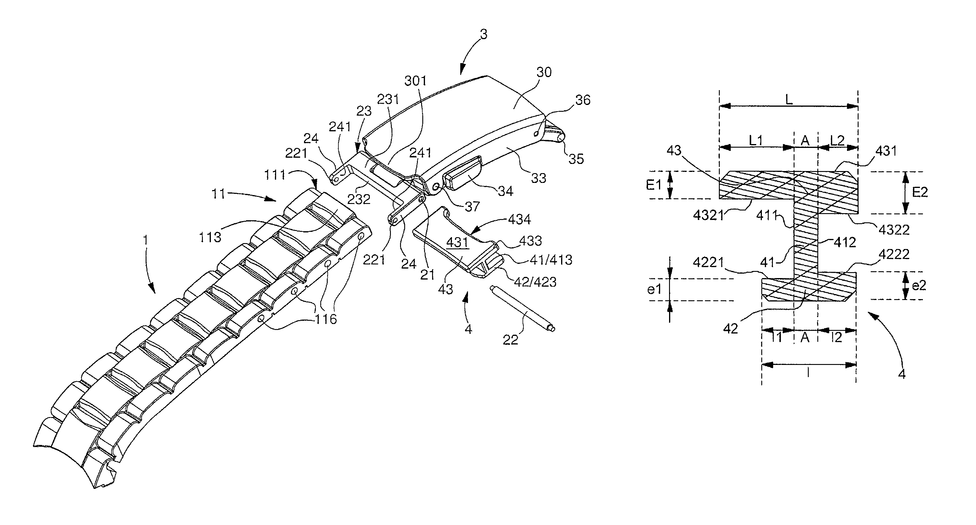
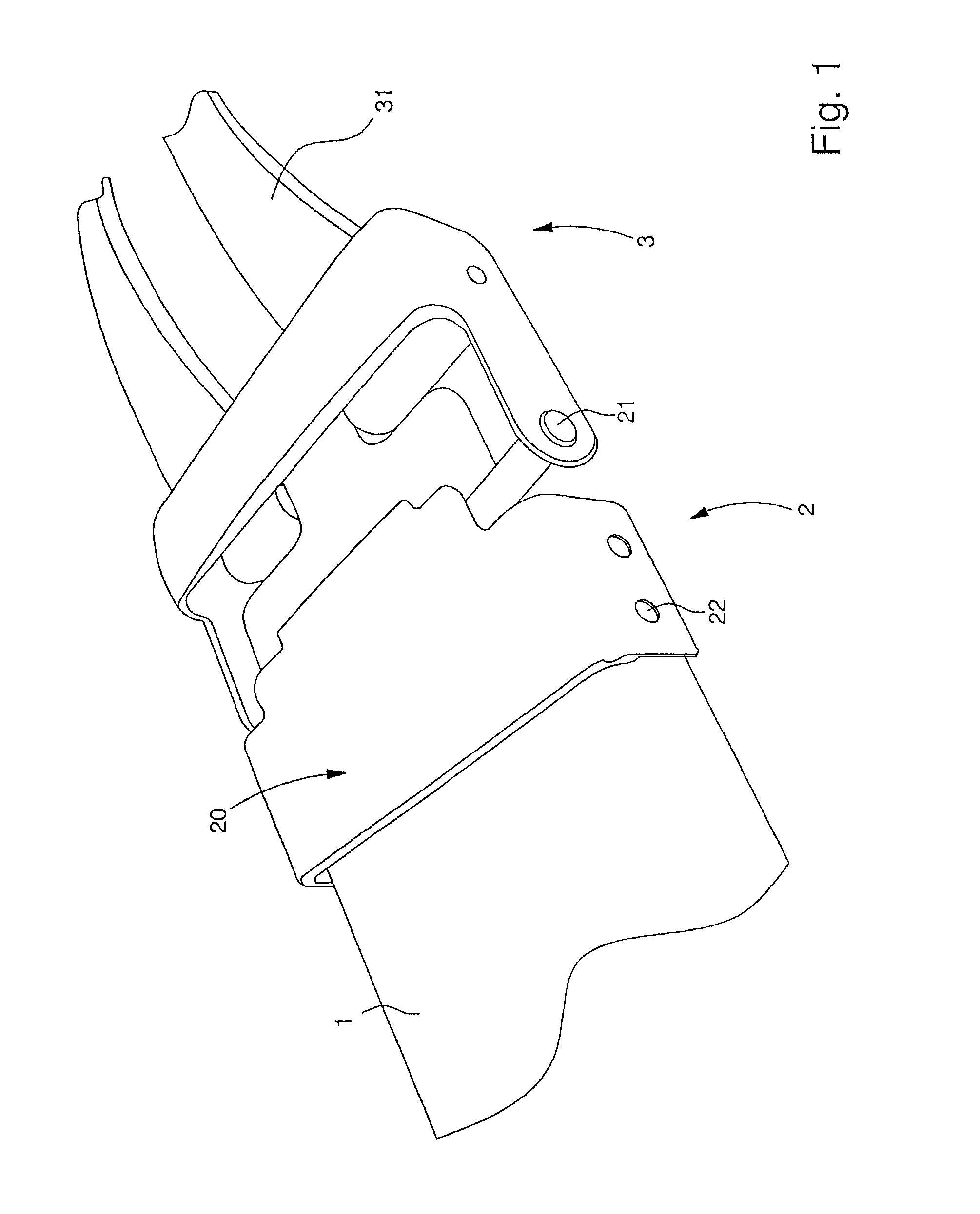
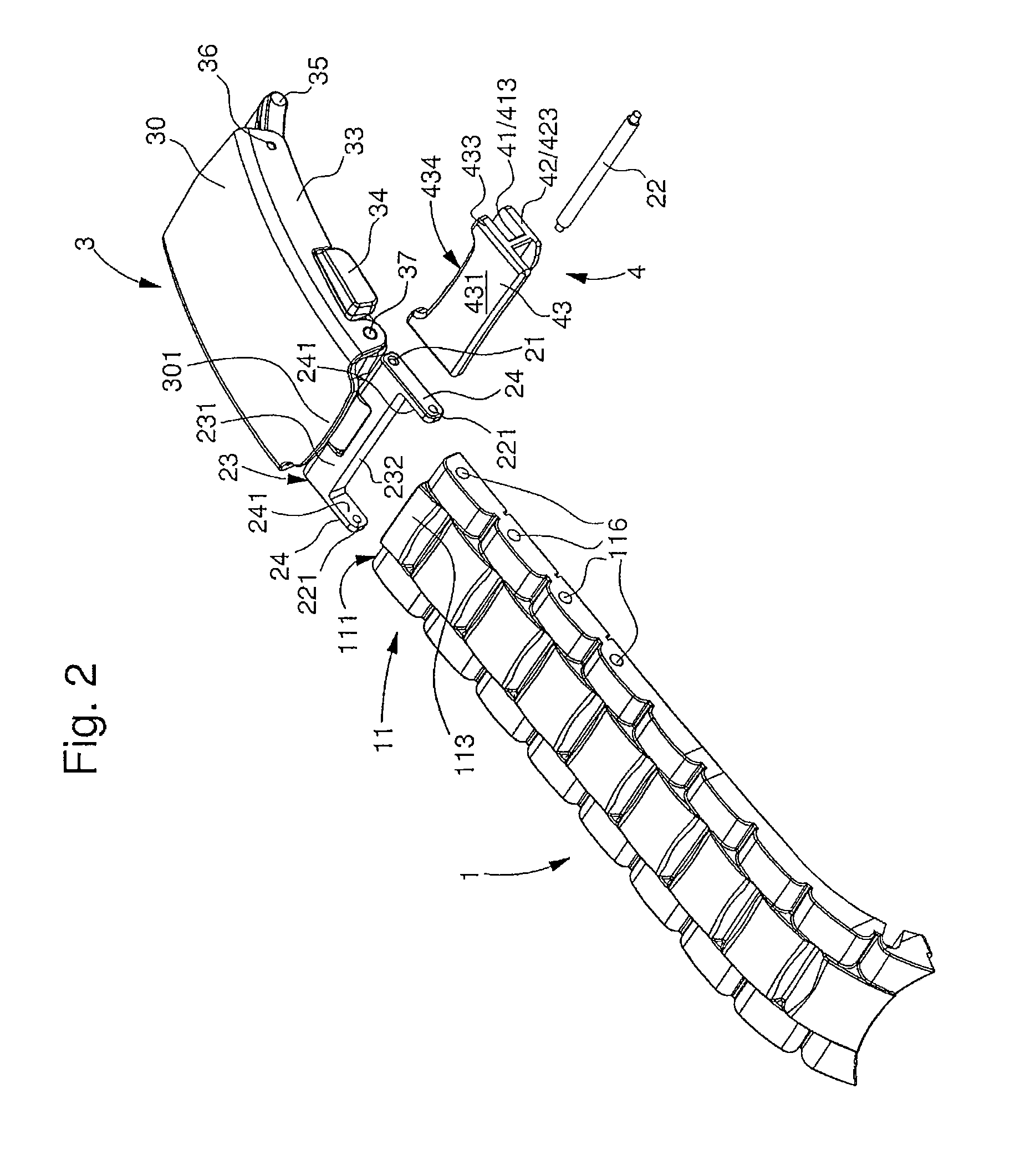
[0021]FIG. 1 illustrates an example of the modified attachment piece 2 known from the prior art for a deployment clasp closure and intended for use with a rubber watch band. The shown closure 3 classically comprises two folding tabs that only occupy a single thickness in folded position, in this case a shaft 31 formed from two arms, between which a central tab (not shown because the closure is shown in deployed position) comes to rest. The shaft 31 is mounted to be movable around a connecting pin to a piece of the closure, which is itself articulated to an attachment piece of the strand 2. The rotation axis between the closure 3 and the attachment piece of the strand 2 is embodied by reference 21 in this figure. The end of a strand 1 of the watch band is connected to the attachment piece 2 by means of a connector bar 22. In order to conceal the cut edge of the end of the strand 1, a screening surface 20 is arranged on an upper face of the attachment piece 2. Moreover, to prevent any...


PUM


Abstract

Link for a wristwatch, characterized in that it comprises a central core connecting a lower wing and an upper wing.

Description

[0001]This application claims priority from European Patent Application No. 11194104.3 filed Dec. 16, 2011, the entire disclosure of which is incorporated herein by reference.FIELD OF THE INVENTION[0002]The present invention relates to a special link for a wristwatch. The present invention also relates to a system for attaching a watch band strand to a closure comprising such a link.BACKGROUND OF THE INVENTION[0003]So-called deployment clasp closures are known in the prior art that allow the watch to be threaded on easily when the clasp is folded out and to then tighten the wrist band in closed position. This type of closure generally comprises a metal cover that closes over the folding tabs, one end of which is attached to the end of one of the strand of the watch band, while the end of the other strand is fixed to an end of the cover. The fastener can be locked by means of a pushbutton mechanism acting in a transverse direction.[0004]Such closures are often used in combination wit...

Claims


Application Information

Patent Timeline
Patent Type & Authority Patents(United States)
IPC IPC(8): A44C5/02A44C5/10A44C5/24
CPCA44C5/185A44C5/02A44C5/0053A44C5/14A44C5/24Y10T24/4718Y10T24/4782
Inventor KALTENRIEDER, CEDRIC
Owner THE SWATCH GROUP MANAGEMENT SERVICES
Why Eureka
Try Eureka