
Bur guide attachment and method of use

a technology of surgical instruments and attachments, applied in the field of surgical instruments, can solve the problems of difficult visualization of precise areas, difficult control of bone cutting tools, and damage to surrounding bones, and achieve the effect of reducing the generation of debris

Inactive Publication Date: 2013-12-17
MAXX ORTHOPEDICS INC
View PDF2 Cites 0 Cited by
  • Summary
  • Abstract
  • Description
  • Claims
  • Application Information

AI Technical Summary

Benefits of technology

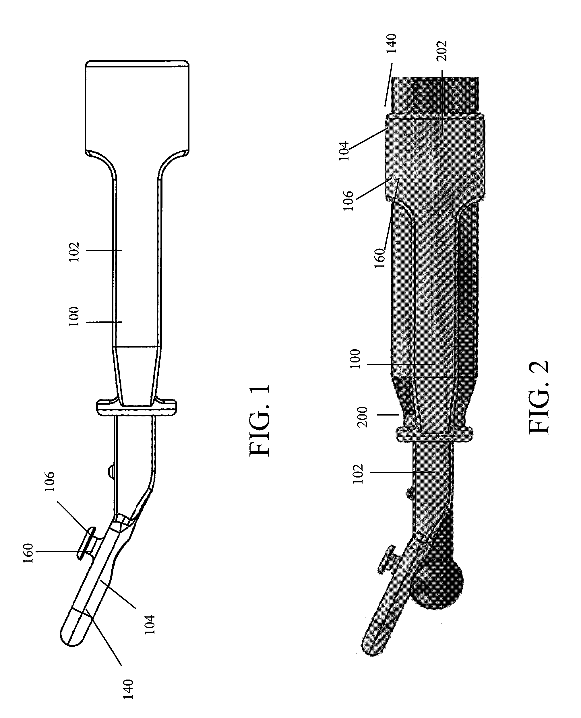
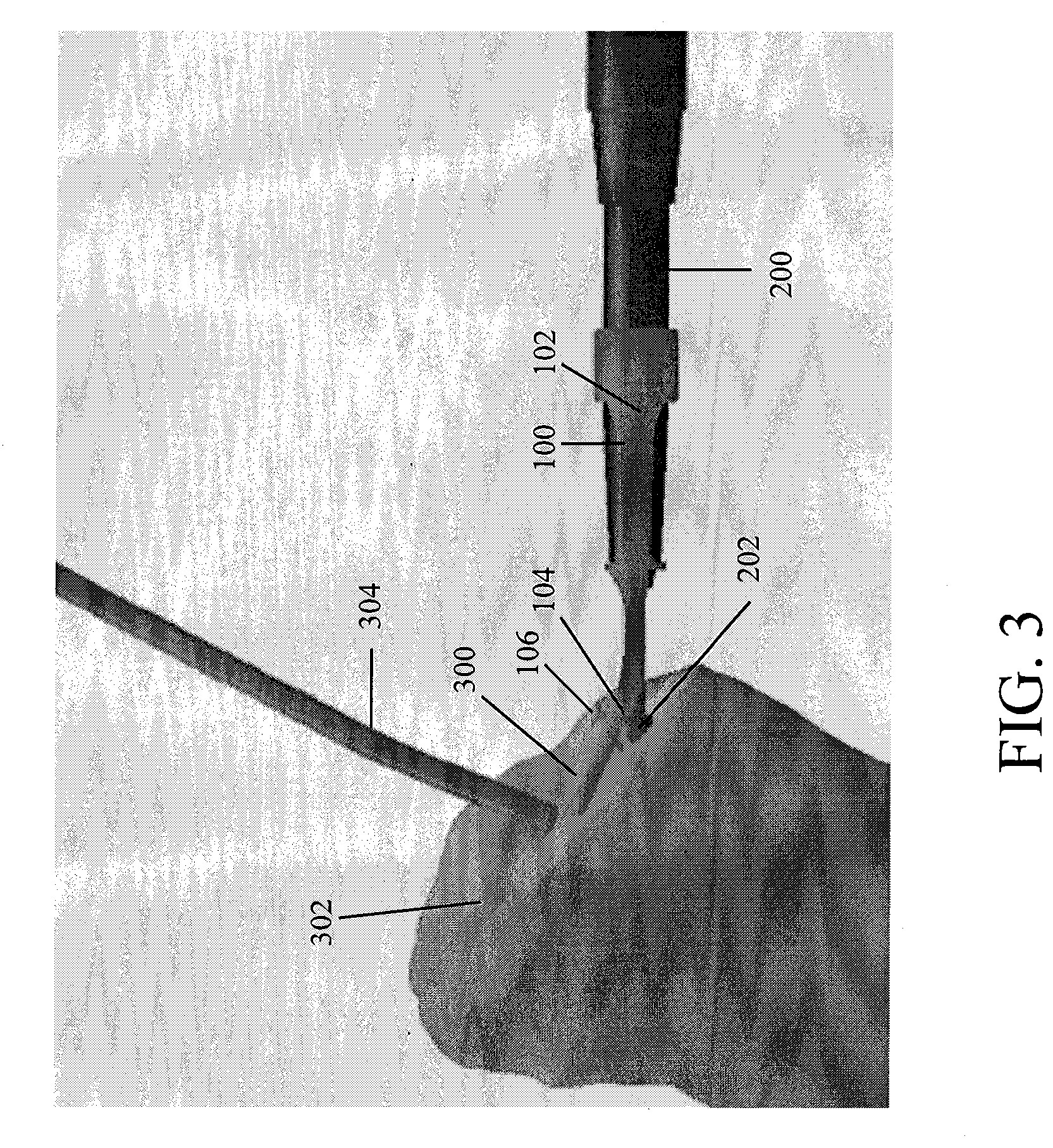
The patent describes a guide for surgical instruments that helps to protect the surgeon from injury and debris during a procedure. The guide includes a cutting member, a guard to resist rotational forces, a rounded edge to prevent contact with other surgical instruments, and a projection member to help with bone penetration. The guide also has a recessed portion to hold the cutting member, and a tether for easy attachment to the patient's anatomy. The technical effects of this guide include increased safety, reduced debris, and improved precision during surgery.

Problems solved by technology

Any damage to the surrounding bone can compromise or weaken the remaining bone and subsequent bone-implant interface.
However, it is often difficult to visualize the precise area of the bone to be resected and bone cutting tools can be difficult to control and may kick away from the desired path unexpectedly.
The use of cutting devices can result in resections that are too deep, improperly shaped, have the wrong orientation, or are in the wrong location, damaging surrounding tissue.
Therefore, it is difficult to remove the proper amount and area of bone necessary for the implant.
However, contact with the rim can result in unwanted debris in the implantation site.
The rim may also be bent or improperly placed, leading to an improperly shaped implant site.
The metal rim is also bulky and awkward to implement as the template has to be larger than the area to be resected.
The computerized systems are expensive, and can still result in improperly shaped resections, particularly resections that are too deep.

Method used


Image

  • Bur guide attachment and method of use
  • Bur guide attachment and method of use
  • Bur guide attachment and method of use

Examples


Embodiment Construction

[0026]For the purposes of promoting an understanding of the principles of the bur guide attachment, reference will now be made to the embodiments, or examples, illustrated in the drawings and specific language will be used to describe these. It will nevertheless be understood that no limitation of the scope of the invention is thereby intended. Any alterations and further modifications in the described embodiments, and any further applications of the principles of the invention as described herein are contemplated as would normally occur to one skilled in the art to which the bur guide attachment invention relates.

[0027]In this detailed description and the following claims, the words proximal, distal, anterior, posterior, medial, lateral, superior and inferior are defined by their standard usage for indicating a particular part of a surgical instrument or surgical opening according to the relative disposition of the surgical instrument, surgical opening or directional terms of refer...


PUM


Abstract

The invention provides a guide for controlling a surgical instrument, that includes a cutting member configured to resect a portion of anatomy and a sheath. The sheath may have a circular connecting portion with an inner diameter substantially the same as the outer diameter of the surgical instrument to receive the surgical instrument. The sheath may also include at least two distally extending arms connected to the circular connecting portion and a ring connected to the distal portion of the at least two distally extending arms. The sheath may also include a distally extending extension connected to the ring. The guide has a superiorly extending guard connected to the distal portion of the extension and a projection member positioned on a superior surface of the guard. The projection member includes a generally circular base and circular platform that has a diameter larger than the generally circular base.

Description

CROSS REFERENCE TO RELATED APPLICATION[0001]This application is related to U.S. provisional patent application No. 61 / 388,828 filed on Oct. 1, 2010, the entirety of which is hereby incorporated by reference.TECHNICAL FIELD[0002]This invention relates generally to the field of surgical instruments, and more specifically, to the field of attachments to guide and control the motion of surgical instruments.BACKGROUND OF THE INVENTION[0003]Surgical procedures often require the removal of a section of bone in order to make room for an implant. In these procedures it is often necessary to remove only a specific area of the bone without harming or damaging the remaining bone stock. Any damage to the surrounding bone can compromise or weaken the remaining bone and subsequent bone-implant interface. However, it is often difficult to visualize the precise area of the bone to be resected and bone cutting tools can be difficult to control and may kick away from the desired path unexpectedly. The...

Claims


Application Information

Patent Timeline
Patent Type & Authority Patents(United States)
IPC IPC(8): A61F5/00
CPCA61B17/1675A61B17/1764
Inventor BLAKEMORE, DAVIDLUCAS, ERIC M.PENNINGTON, KEITH E.
Owner MAXX ORTHOPEDICS INC
Learn More