
Web-winding device

a technology of winding device and web, which is applied in the direction of optics, instruments, film packaging, etc., can solve the problems of high production loss, affecting the overall mechanical performance of the hip, and generating a tremendous amount of hip dust and debris, so as to resist the core crush, and improve the overall mechanical performance

Inactive Publication Date: 2007-03-20
EASTMAN KODAK CO
View PDF9 Cites 0 Cited by
  • Summary
  • Abstract
  • Description
  • Claims
  • Application Information

AI Technical Summary

Benefits of technology

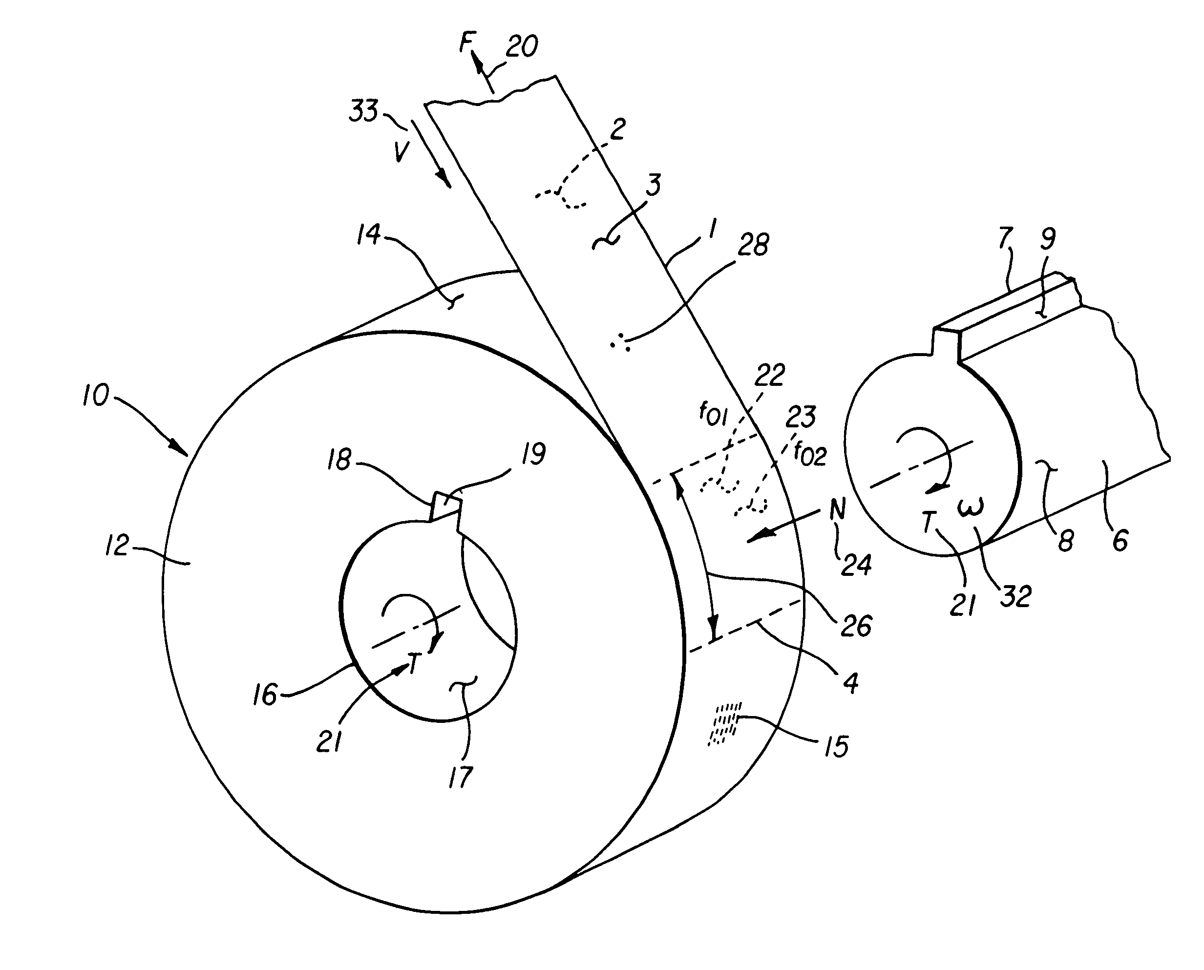
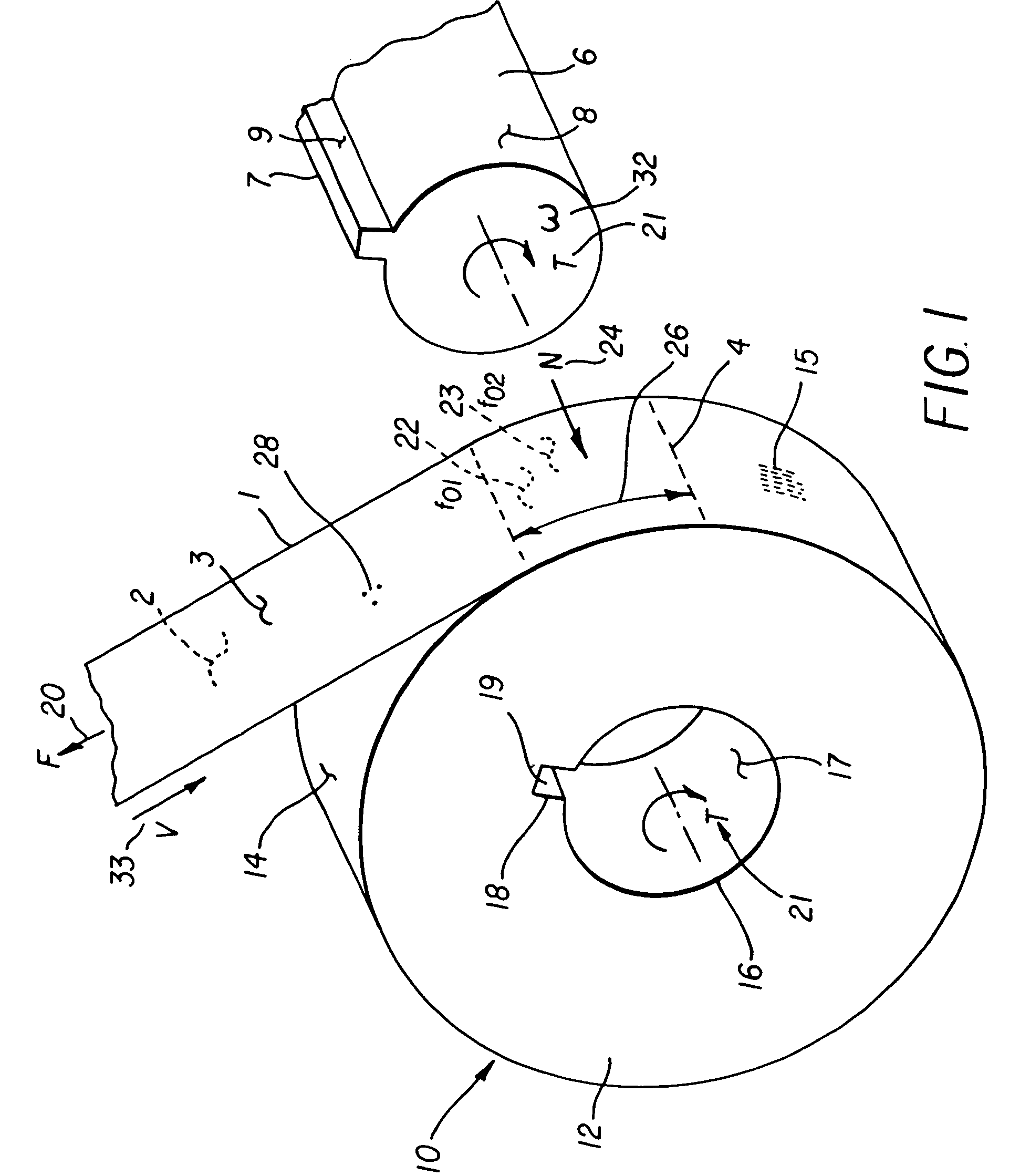
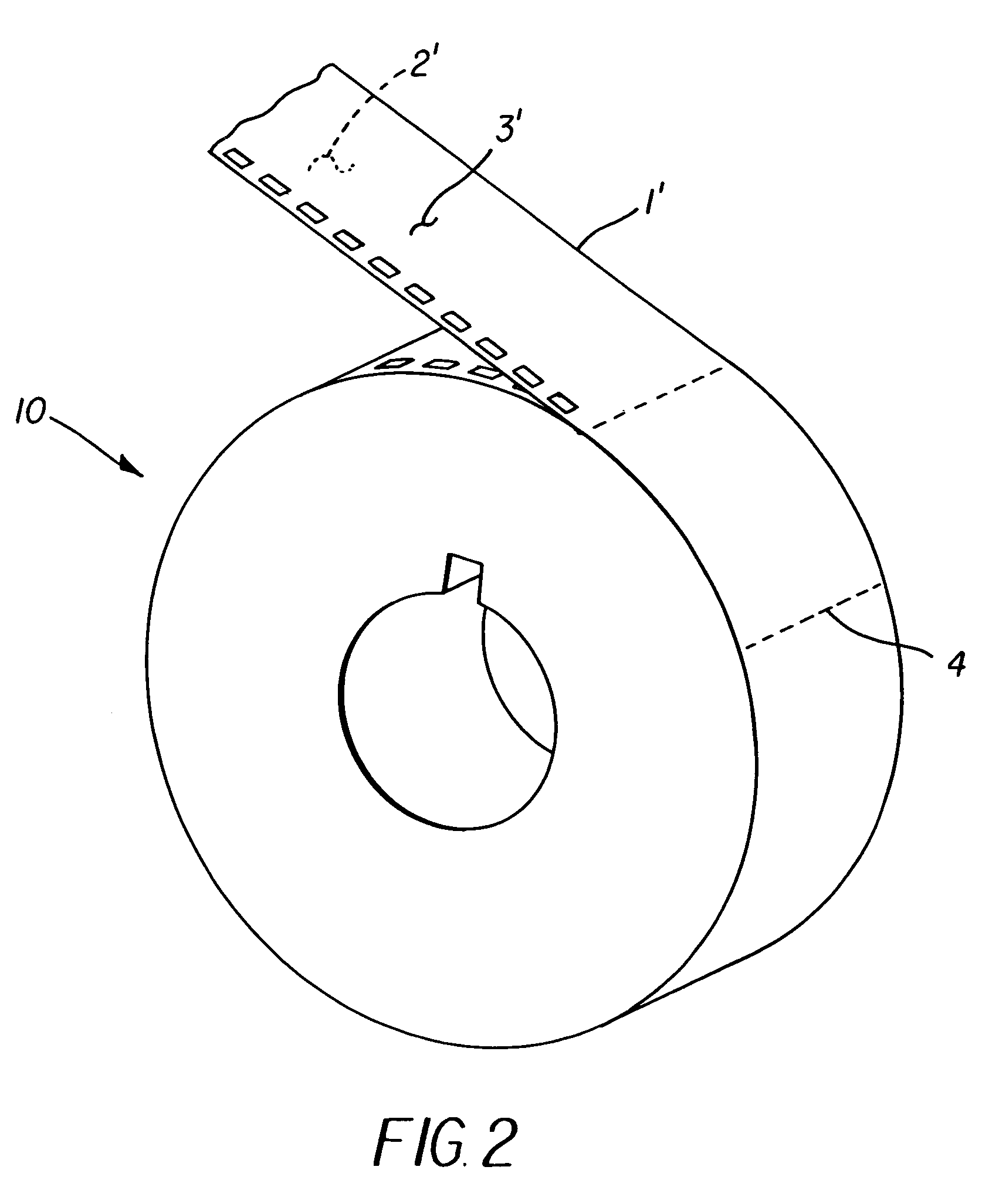
The present invention provides a durable and less debris-generating web-winding means with superior mechanical integrity. The device has a cylindrical support structure with an inner annular surface that mates with a web-winding machine. The inner annular surface has a wear rate coefficient of less than about 3.0×10⁻⁷ m3 / Nm. The device has advantages such as improved overall mechanical properties, a stronger core, lower friction and wear, and an enhancement in surface finish. These features facilitate the cinching of the leader portion of the film and enable the reuse of cores.

Problems solved by technology

The high speed of the spooling process combined with the poor overall wear property of the current thermoplastic HIPS resin result in the generation of a tremendous amount of HIPS dust and debris at the mounting interface of the core with the winding machine spindle.
The generation of this level of debris creates high production losses and nightmarish housekeeping issues.
Core crush, a form of permanent deformation, is exemplary of the damage from handling where a fully spooled motion picture core sustains sufficient impact energy to literally crush the core resulting in complete failure of the part.
Needless to say, this form of damage is particularly costly and frustrating to motion picture printing customers because: 1) film telescopes and comes off of whatever is left of the damaged core; and / or 2) the core cannot be installed onto the winding spindle.

Method used


Image

  • Web-winding device
  • Web-winding device
  • Web-winding device

Examples


example

[0054]GE Plastics “LEXAN EXL”; and

[0055](3) PTFE filled polycarbonate (amorphous polyester).

examples

[0056]GE Plastics “LEXAN WR2210” with 15 percent by weight PTFE.

[0057]Referring to FIG. 8, the preferred embodiment of this invention comprises an injection molded web-winding means 10′ for a photographic web 1′ comprised of a plurality of cored segments 40 forming an outer web-winding surface wall thickness 44, an inner annular portion wall thickness 42, and a plurality of support ribs 46, and a outer web-winding surface to inner annular portion surface connecting portion 48 with a wall thickness 49. The web-winding means 10 preferably conforms to dimensions per ISO international standard ISO 1039 “Cinematography—Cores for Motion-Picture And Magnetic Film Rolls—Dimensions” and the equivalent standard ANSI / SPTME 37M “SMPTE Standard for Motion-Picture Equipment—Raw Stock Cores”. In particular the preferred embodiment for the invention is a 35 mm×75 mm motion-picture raw stock core. Outer web-winding surface wall thickness 44, the inner annular portion surface wall thickness 42 and th...


PUM

PropertyMeasurementUnit
tensile strengthaaaaaaaaaa
tensile elongationaaaaaaaaaa
flexural strengthaaaaaaaaaa

Abstract

An improved web-winding means with a durable thermoplastic polyester resin or polyester resin blend support structure and web capture slot (gate) formed in an interior portion of the support structure. The interior portion is joined to an inner annular surface that has increased lubricity, toughness and creep resistance resulting in decreased debris generation plus increased structural integrity and dimensional stability.

Description

CROSS-REFERENCE TO RELATED APPLICATIONS[0001]The present application is related to U.S. Ser. No. 10 / 719,120, filed concurrently herewith, of Michael R. McGovern and Edgar G. Earnhart, entitled “A Web-Winding Means”, and[0002]U.S. Ser. No. 10 / 719,578, filed concurrently herewith, of Michael R. McGovern and Edgar G. Earnhart, entitled “Method Of Manufacturing A Web-Winding Device”.FIELD OF THE INVENTION[0003]The invention relates generally to the field of web-winding devices. More particularly, the invention concerns a web-winding means particularly well suited for photographic film material based on silver halide technology.BACKGROUND OF THE INVENTION[0004]Traditionally, motion picture film stock cores, such as those defined by the Society of Motion Picture and Television Engineers (SMPTE) standard ANSI-SMPTE 37M or ISO 1039-1995, have been injection molded from thermoplastic high impact polystyrene (HIPS) molding compounds. The HIPS resin has been the material of choice mostly drive...

Claims


Application Information

Patent Timeline
Patent Type & Authority Patents(United States)
IPC IPC(8): B65H75/14B65H75/10G03C3/00
CPCB65H75/10G03C3/00B65H2701/5122
Inventor MCGOVERN, MICHAEL R.EARNHART, EDGAR G.
Owner EASTMAN KODAK CO
Learn More