Redox flow battery and method of operating the same

a redox flow battery and flow technology, applied in the field of redox flow batteries, can solve the problems of power system operation, difficulty in maintaining frequency and voltage, etc., and achieve the effects of reducing the battery capacity of the redox flow battery, high electromotive force, and reducing the cost of the invention

Active Publication Date: 2014-01-21
SUMITOMO ELECTRIC IND LTD
View PDF20 Cites 3 Cited by
  • Summary
  • Abstract
  • Description
  • Claims
  • Application Information

AI Technical Summary

Benefits of technology

[0041]The redox flow battery of the present invention has a high electromotive force, and is capable of restoring a decreased battery capacity due to charge and discharge. When the battery capacity of the redox flow battery of the present invention decreases due to charge and discharge, the method of operating a redox flow battery of the present invention can restore the decreased battery capacity.

Problems solved by technology

Since outputs of these power generations are affected by the weather, it is predicted that the introduction on a large scale will cause problems with operation of power systems such as difficulty in maintaining frequencies and voltages.

Method used


Image

  • Redox flow battery and method of operating the same
  • Redox flow battery and method of operating the same
  • Redox flow battery and method of operating the same

Examples


first experimental example

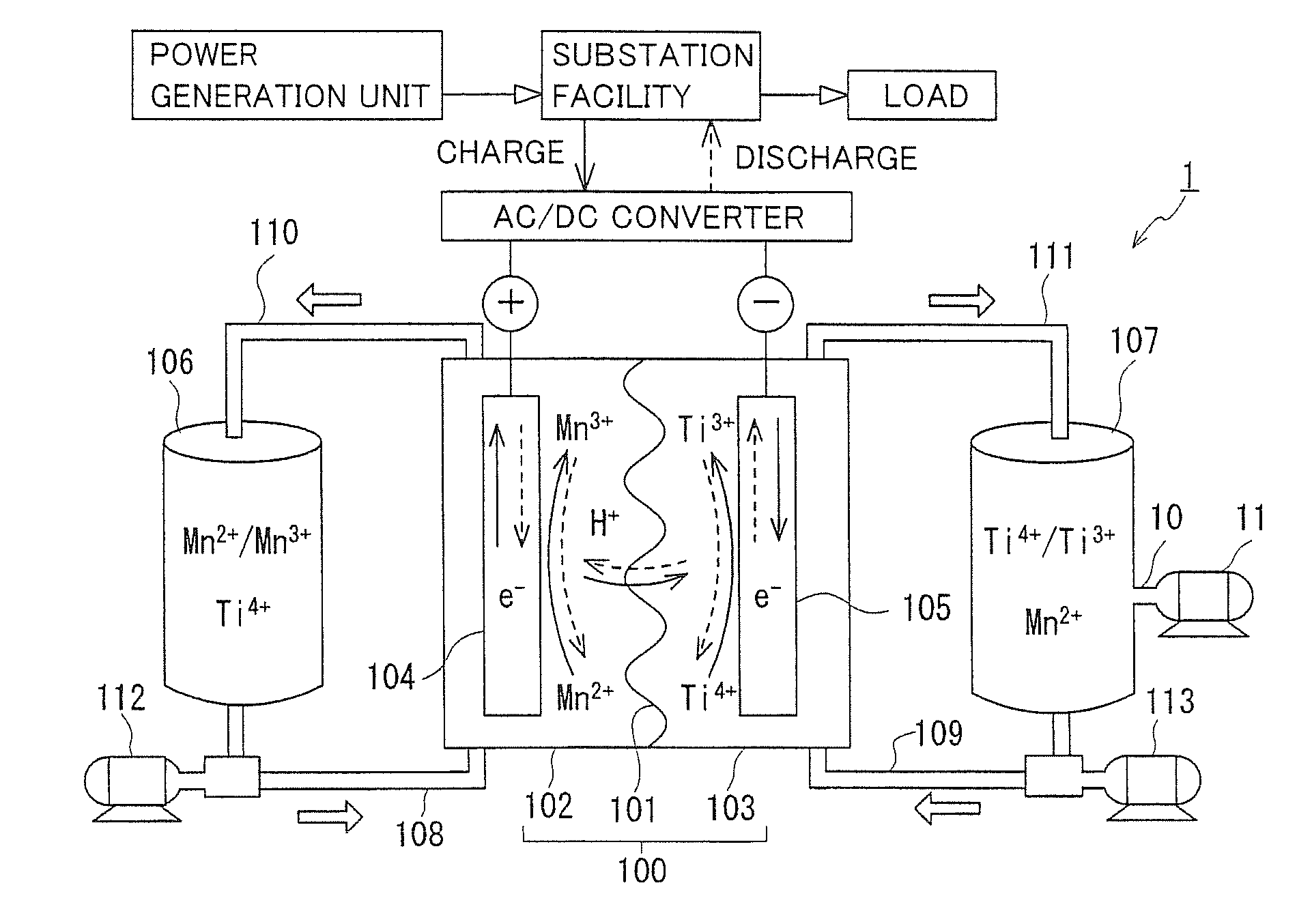
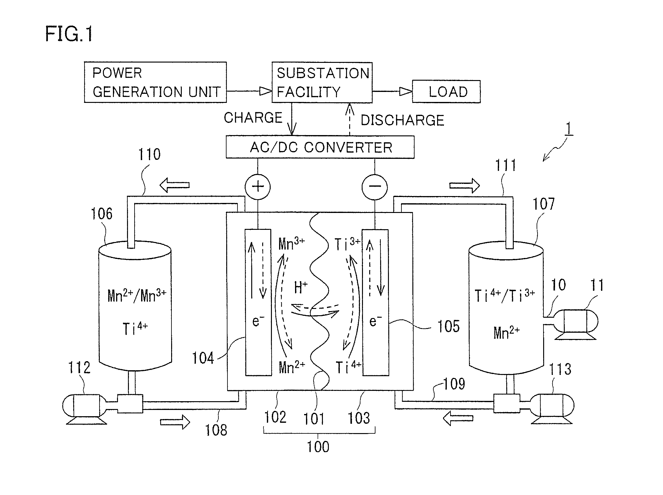
[0081]RF battery 2 having a structure similar to that in the second embodiment described with reference to FIG. 3 was fabricated. As the positive electrode electrolyte and the negative electrode electrolyte, an electrolyte containing sulfuric acid having a concentration of 2M, MnSO4 (Mn2+) having a concentration of 1M, and TiOSO4 (Ti4+) having a concentration of 1M mixed therein was used. Tanks 106 and 107 were filled with 3 L of the positive electrolyte and 3 L of the negative electrolyte, respectively, in an airtight manner from the external atmosphere. The gas phase sections were filled with nitrogen gas in order to suppress oxidation. As battery element 100, a single cell having an electrode area of 500 cm2 employing a carbon felt electrode and a cation exchange membrane was used. Liquid-phase communicating tube 14 and gas-phase communicating tube 13 remained closed.

[0082]This experimentally fabricated Ti / Mn-based RF battery 2 was subjected to charge and discharge tests. The ini...

second experimental example

[0087]RF battery 2 having a structure similar to that in the first experimental example was subjected to charge and discharge tests, with gas-phase communicating tube 13 being opened (liquid-phase communicating tube 14 being closed). As a result, it was confirmed that it took about 90 days after the start of the tests until the battery capacity decreased to about 65% of the initial capacity, indicating a lower rate of decrease in battery capacity of RF battery 2. This result was not sufficient to effectively suppress the decrease in battery capacity of RF battery 2.

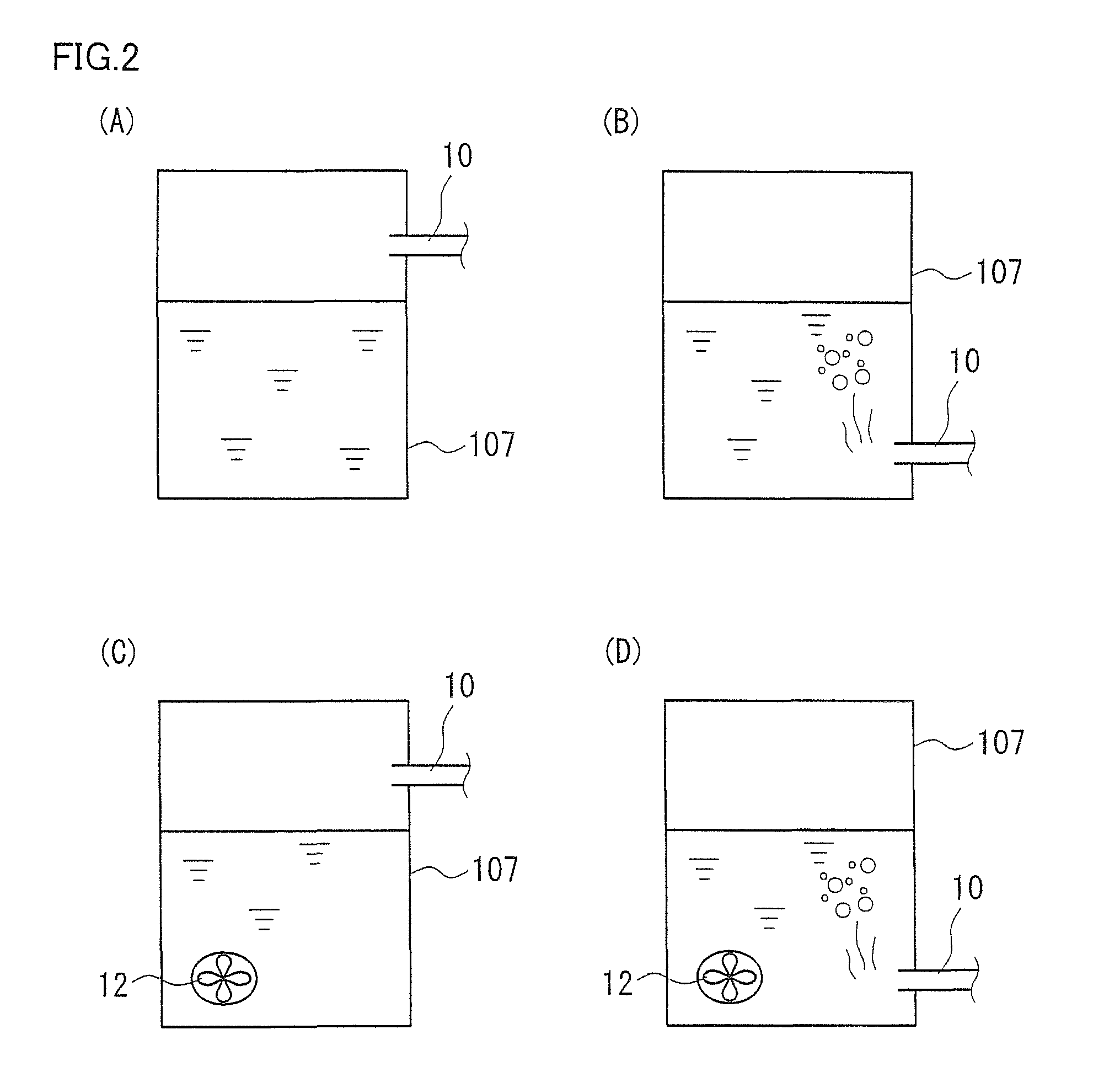
[0088]Therefore, next, charge and discharge (gas-phase communicating tube 13 being opened and liquid-phase communicating tube 14 being closed) was repeated while the air is introduced into negative electrode tank 107 via negative-electrode-side introduction duct 10. As a result, a phenomenon in which the battery capacity was gradually restored was observed. During this time, the degree of restoration of the battery capaci...


PUM

PropertyMeasurementUnit
oxidation-reduction potentialsaaaaaaaaaa
oxidation-reduction potentialaaaaaaaaaa

Abstract

A redox flow battery in which a positive electrode electrolyte stored in a positive electrode tank and a negative electrode electrolyte stored in a negative electrode tank are supplied to a battery element to charge and discharge the battery is provided, the positive electrode electrolyte in the redox flow battery containing a Mn ion as a positive electrode active material, the negative electrode electrolyte containing at least one of a Ti ion, a V ion, and a Cr ion as a negative electrode active material, in which the redox flow battery includes a negative-electrode-side introduction duct in communication with inside of the negative electrode tank from outside thereof, for introducing oxidizing gas into the negative electrode tank, and a supply mechanism for supplying the oxidizing gas into the negative electrode tank via the negative-electrode-side introduction duct.

Description

TECHNICAL FIELD[0001]The present invention relates to a redox flow battery and a method of operating the same. More particularly, the present invention relates to a redox flow battery capable of generating a high electromotive force.BACKGROUND ART[0002]As a way to combat global warming, the introduction of new energy such as solar photovoltaic power generation and wind power generation has been promoted in recent years throughout the world. Since outputs of these power generations are affected by the weather, it is predicted that the introduction on a large scale will cause problems with operation of power systems such as difficulty in maintaining frequencies and voltages. As a way to solve such problems, the installation of large-capacity storage batteries for smoothing output variations, storing surplus power, and load leveling is expected.[0003]A redox flow battery is one of large-capacity storage batteries. In a redox flow battery, a positive electrode electrolyte and a negative...

Claims


Application Information

Patent Timeline
Patent Type & Authority Patents(United States)
IPC IPC(8): H01M2/36H01M4/36
CPCH01M8/04753H01M8/188H01M8/04761H01M8/04798H01M8/04089H01M8/20H01M8/04805Y02E60/528Y02E60/50H01M8/04H01M8/18
Inventor DONG, YONGRONGSHIGEMATSU, TOSHIOKUMAMOTO, TAKAHIRO
Owner SUMITOMO ELECTRIC IND LTD
Why Eureka
Try Eureka