Free-end magnetic circuit adjusting cantilever beam vibration energy collecting device

A technology of vibration energy collection and cantilever beam, applied in the direction of electromechanical devices, electrical components, etc., can solve the problems of the magnetic force of the components hindering vibration, reducing the magnetic induction intensity, and not realizing the closed magnetic circuit, so as to improve the energy conversion efficiency and facilitate the vibration Effect

Pending Publication Date: 2018-10-09
ZHEJIANG UNIV OF TECH
View PDF5 Cites 1 Cited by
  • Summary
  • Abstract
  • Description
  • Claims
  • Application Information

AI Technical Summary

Problems solved by technology

[0006] 2. The volatility is relatively large
[0008] In addition to the above two papers, there are still a large number of published documents on electromagnetic vibration energy harvesting devices with cantilever beam and fixed beam structure, but they all have common defects: first, the closed magnetic circuit is not realized, that is, the magnetic field lines are in the air and other magnetic fields. If a medium with a large resistance passes through a long distance, it will inevitably reduce the magnetic induction intensity, which is extremely unfavorable for increasing the power generation. On the contrary, if the closed magnetic circuit is realized, the power generation will be greatly increased; secondly, some components in the magnetic circuit (including the coil) in the device Participate in the vibration, some do not participate, causing the problem that the magnetic force between the components hinders the vibration

Method used


Image

  • Free-end magnetic circuit adjusting cantilever beam vibration energy collecting device
  • Free-end magnetic circuit adjusting cantilever beam vibration energy collecting device
  • Free-end magnetic circuit adjusting cantilever beam vibration energy collecting device

Examples


Embodiment Construction

[0030] The present invention will be further described below in conjunction with the accompanying drawings.

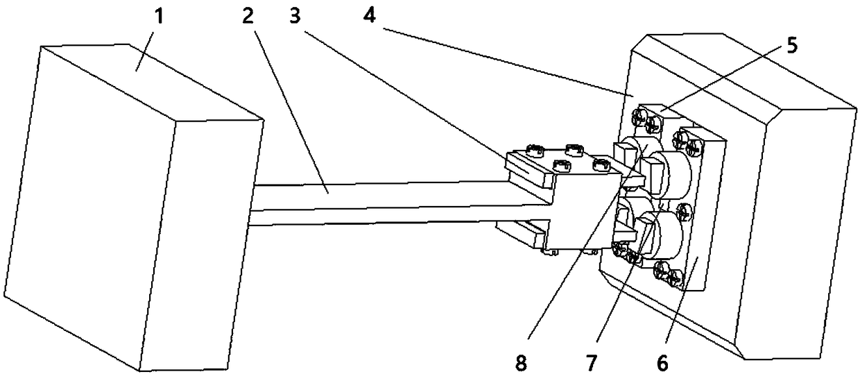
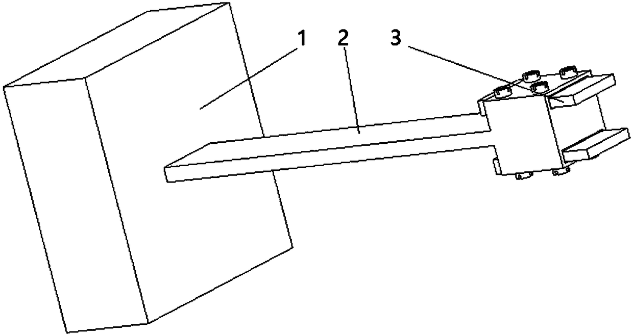
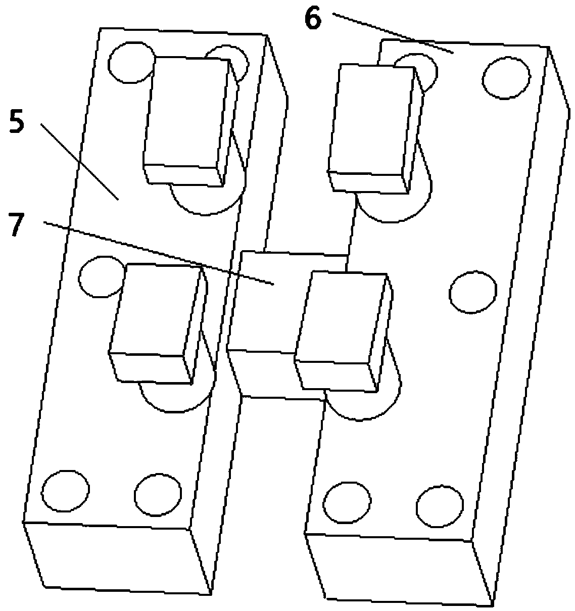
[0031] refer to Figure 1 ~ Figure 4, a free-end magnetic circuit-adjusted cantilever beam vibration energy harvesting device, which will generate a certain continuous free vibration under external excitation, and collect energy through an electromagnetic device with a closed magnetic circuit as a low-power wireless sensor node, IoT node power supply. The specific structure is described below:

[0032] The device has a cantilever beam fixed end 1, see figure 1 and figure 2 , as the installation position of the entire cantilever beam, it is made of non-magnetic material, non-magnetic, and requires firmness and stability.

[0033] Further, the cantilever beam 2 is inserted at one end and firmly installed at the fixed end of the cantilever beam, see figure 1 and figure 2 , is made of non-magnetic material and requires non-magnetic conduction; at the same time, the...


PUM


Abstract

A free-end magnetic circuit adjusting cantilever beam vibration energy collecting device is disclosed. One end of a cantilever beam is inserted into and is fixedly arranged on the fixing end of the cantilever beam. The cross section of the cantilever beam is in a rectangular shape. The tail of the cantilever beam is provided with a counterweight. Two cantilever beam magnet yokes are installed andfixed on the counterweight. A permanent magnet fixing end is close to the free end of the cantilever beam. The fixing end of a permanent magnet is horizontally and symmetrically installed and fixed with a left permanent magnet yoke and a right permanent magnet yoke. A gap is arranged between the left permanent magnet yoke and the right permanent magnet yoke. One side of the left permanent magnet yoke and one side of the right permanent magnet yoke, which are close to the cantilever beam, are provided with two coil supports which are vertically distributed respectively. The left permanent magnet yoke and the right permanent magnet yoke are installed with the permanent magnets. An induction coil is wound on the installation shaft of the two coil supports in each of the left permanent magnetyoke and the right permanent magnet yoke. The two leading-out terminals of the induction coil are connected to an energy collecting circuit. In the invention, energy conversion efficiency is high andvibration damping is small.

Description

technical field [0001] The invention relates to the field of electromagnetic energy collection devices, in particular to a device for collecting energy by vibration of a cantilever beam. Background technique [0002] There are a large number of distributed IoT nodes and wireless sensor nodes in the Internet of Things and wireless sensor networks. The above-mentioned nodes all need their own independent power supply devices. Currently, batteries are mostly used, which has some negative effects: First, The battery power is limited, which limits the service life of nodes; second, the secondary pollution caused by chemical batteries poses a threat to the natural environment and the organisms in it. In view of the above problems, it is of great significance to study energy harvesting technology to use renewable energy to realize the self-power supply of IoT nodes. [0003] There may be a variety of vibration sources in life, for example, the main vibration frequency of washing m...

Claims


Application Information

Patent Timeline
Patent Type & Authority Applications(China)
IPC IPC(8): H02K35/02
CPCH02K35/02
Inventor 张端孙莹
Owner ZHEJIANG UNIV OF TECH
Why Eureka
Try Eureka