Fractional-slot concentrated winding permanent magnet synchronous motor and design method thereof for improving reluctance torque

A permanent magnet synchronous motor, concentrated winding technology, applied to synchronous motors with stationary armatures and rotating magnets, shapes/styles/structures of winding conductors, magnetic circuit rotating parts, etc. Low resistance torque, etc., to reduce the risk of short-circuit between phases, reduce losses, and achieve the effect of phase-to-phase isolation

Inactive Publication Date: 2018-06-22
JIANGSU UNIV
View PDF3 Cites 12 Cited by
  • Summary
  • Abstract
  • Description
  • Claims
  • Application Information

AI Technical Summary

Problems solved by technology

[0004] The purpose of the present invention is to solve the problem of low reluctance torque of permanent magnet synchronous motor with fractional slot concentrated winding, and propose a simple, effective and easy-to-execute method

Method used


Image

  • Fractional-slot concentrated winding permanent magnet synchronous motor and design method thereof for improving reluctance torque
  • Fractional-slot concentrated winding permanent magnet synchronous motor and design method thereof for improving reluctance torque
  • Fractional-slot concentrated winding permanent magnet synchronous motor and design method thereof for improving reluctance torque

Examples


Embodiment Construction

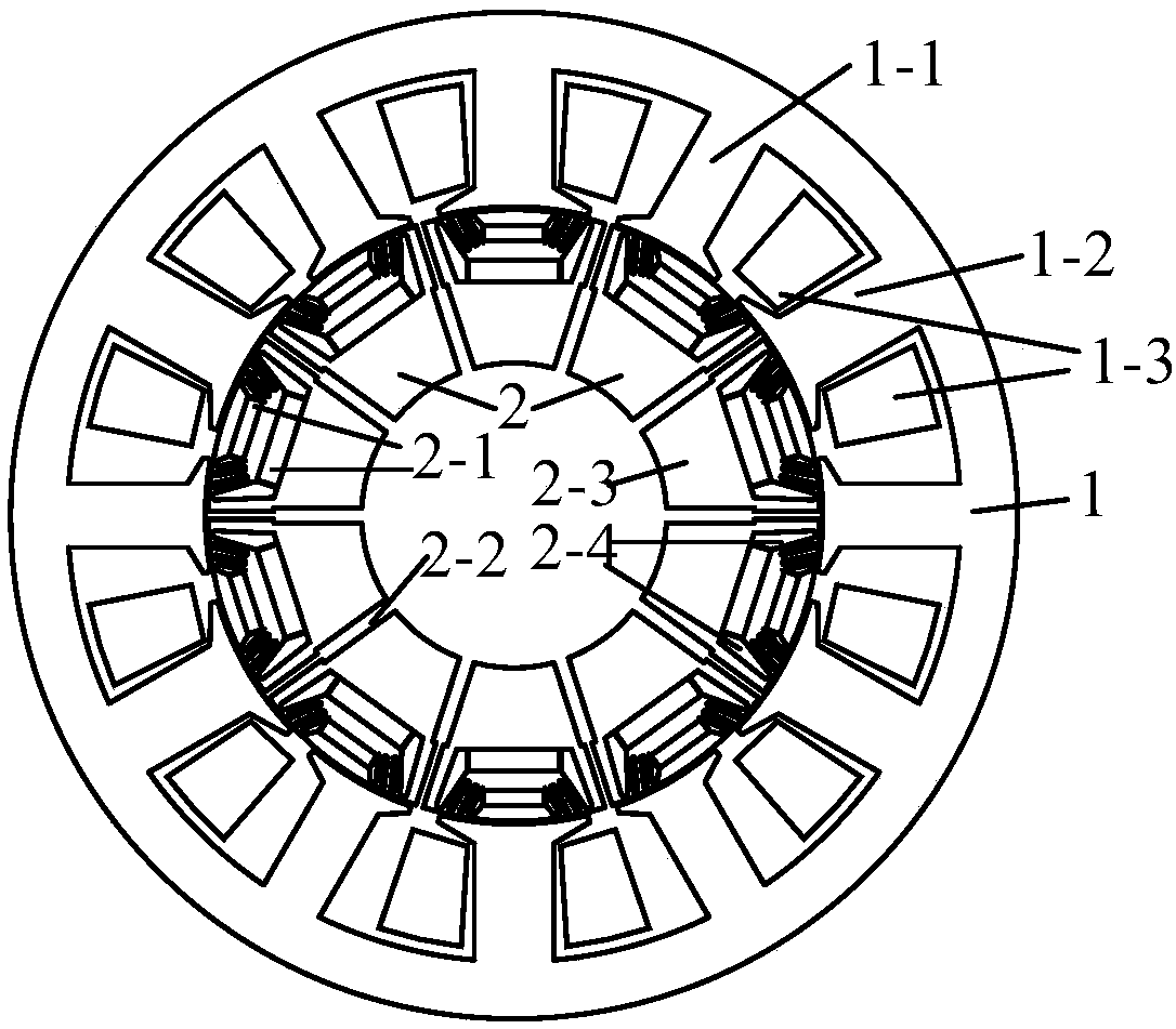
[0031] Please refer to figure 1 , the present invention is a method for increasing the reluctance torque of a fractional slot concentrated winding permanent magnet synchronous motor with high reluctance torque ratio, mainly by increasing the reluctance of the direct-axis magnetic circuit and reducing the direct-axis inductance to achieve the design purpose. The structure of the present invention includes a stator 1 and a rotor 2. There is an air gap between the stator 1 and the rotor 2, and the length of the air gap is selected according to the motor structure and actual requirements.

[0032] Take a 12-slot 10-pole motor as an example, figure 1 It is a structural schematic diagram of a new fractional slot concentrated winding permanent magnet synchronous motor. The stator 1 includes two structures of a fault-tolerant tooth 1-1 and an armature tooth 1-2. The armature winding 1-3 is wound on the armature teeth 1-2. The tooth width ratio of the armature tooth and the toleranc...


PUM


Abstract

The invention discloses fractional-slot concentrated winding permanent magnet synchronous motor and a design method thereof for improving reluctance torque. The fractional-slot concentrated winding permanent magnet synchronous motor comprises a stator and a rotor, wherein the stator is slotted along the peripheral direction to form fault-tolerant teeth and armature teeth arranged alternately; an armature winding is wound on the armature teeth, the fault-tolerant teeth and the armature teeth are different in widths, and the widths of the armature teeth are wider than those of the fault-tolerantteeth; the rotor consists of a permanent magnet, a rotor core and a magnetic obstacle, the permanent magnet is a double-layer permanent magnet, the rotor core is composed of a plurality of independent units, and during machining, the rotor is wrapped with a non-metal material to form a compact structure. The rotor core is segmented along the axis pole direction of the permanent magnet, and the width of the upper part of the magnetic obstacle during segmentation is narrower than that of the lower part. The permanent magnet synchronous motor has the advantages that the direct-axis inductance can be reduced through the special magnetic obstacle design, the influence on quadrature axis inductance can also be reduced as much as possible, and the subharmonic of the motor is free of obvious inhibition. Therefore, the reluctance torque of the motor can be improved effectively, and the iron loss and eddy-current loss of the motor are reduced.

Description

technical field [0001] The invention relates to a motor manufacturing technology, in particular to a technology for improving the reluctance torque of a fractional slot concentrated winding permanent magnet synchronous motor. Background technique [0002] The fractional slot concentrated winding permanent magnet synchronous motor has many characteristics such as short winding ends, low copper consumption, high efficiency, and good fault tolerance. Therefore, it has good application scenarios in many occasions such as aerospace, ship propulsion, and industrial drives. At present, the biggest challenge facing permanent magnet synchronous motors with fractional slot concentrated windings is the improvement of reluctance torque. The main component of the torque of the traditional fractional slot concentrated winding permanent magnet synchronous motor is the permanent magnet torque, which makes it difficult for the motor to weaken the field at high speed, thus limiting the speed ...

Claims


Application Information

Patent Timeline
Patent Type & Authority Applications(China)
IPC IPC(8): H02K1/16H02K3/28H02K3/12H02K1/27H02K21/14H02K15/00
CPCH02K1/165H02K1/276H02K3/12H02K3/28H02K15/00H02K21/14
Inventor 吉敬华张新星
Owner JIANGSU UNIV
Why Eureka
Try Eureka