Synchronous reluctance motor rotor applied to hybrid power system

A technology of synchronous reluctance motor and hybrid power system, applied in the direction of synchronous machine parts, electrical components, electromechanical devices, etc., can solve the problems of reduced bearing life, shortened motor life, narrow constant power speed regulation range, etc., to reduce the use of Quantity, cost saving effect

Inactive Publication Date: 2015-07-29
TIANJIN SANTROLL ELECTRIC AUTOMOBILE TECH CO LTD
View PDF0 Cites 11 Cited by
  • Summary
  • Abstract
  • Description
  • Claims
  • Application Information

AI Technical Summary

Problems solved by technology

[0002] Existing drive motors for vehicles are generally AC asynchronous motors and permanent magnet synchronous motors. AC asynchronous motors are simple in structure and reliable in operation, but have low power density and narrow constant power speed regulation range. The heat generated by the rotor is transmitted to the bearing, which will greatly reduce the life of the bearing, thereby shortening the overall life of the motor; although the permanent magnet synchronous motor has high efficiency, high power density, and a wide range of constant power speed regulation, the heat generated by the rotor is relatively low....

Method used


Image

  • Synchronous reluctance motor rotor applied to hybrid power system
  • Synchronous reluctance motor rotor applied to hybrid power system
  • Synchronous reluctance motor rotor applied to hybrid power system

Examples


Embodiment Construction

[0024] The concrete implementation method of the present invention is as follows:

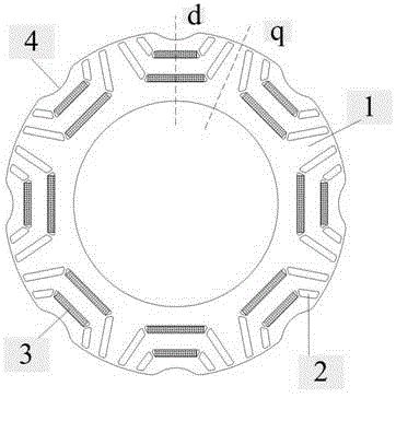
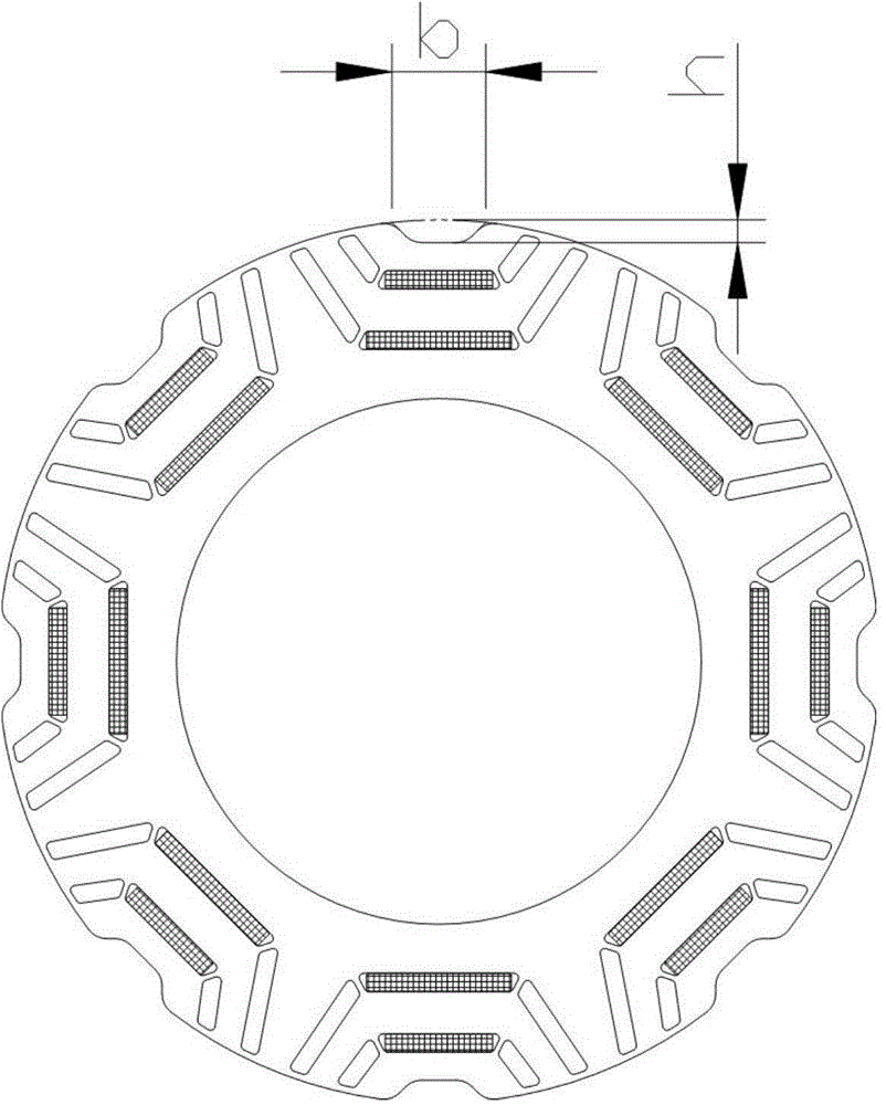
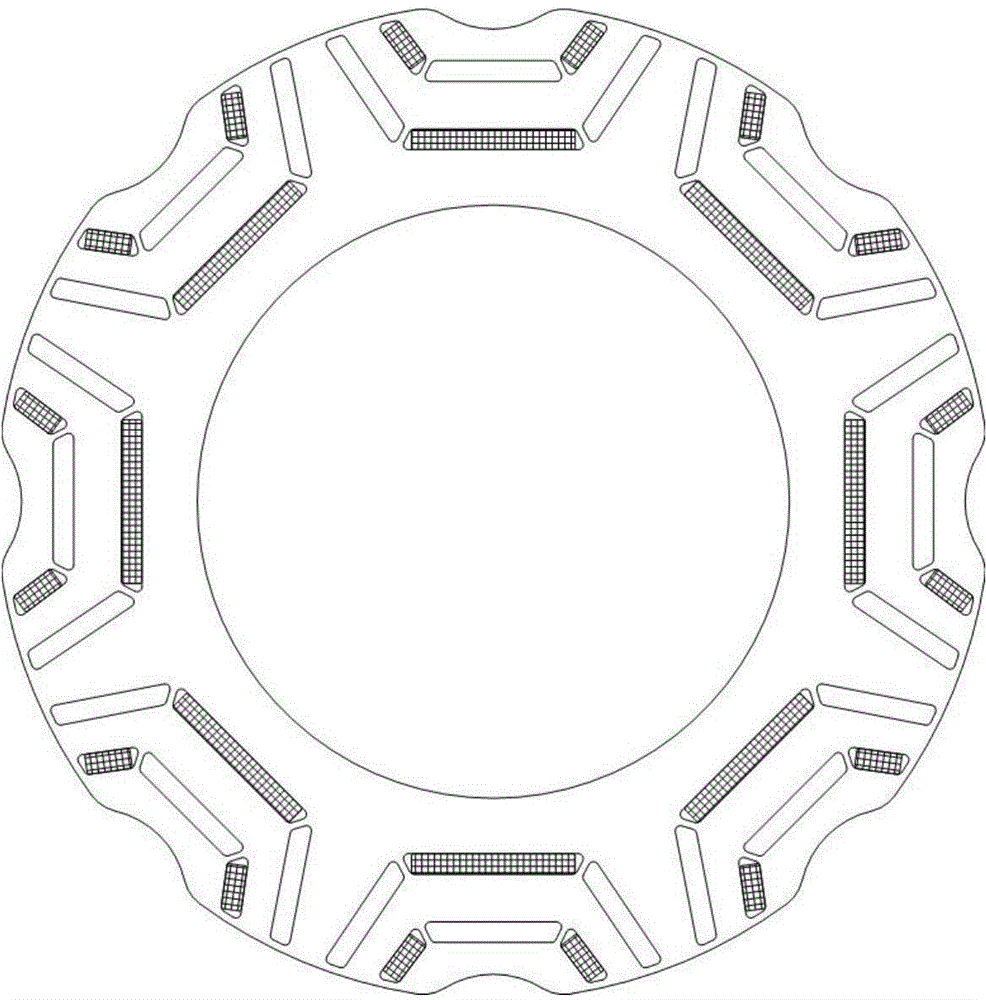
[0025] The synchronous reluctance motor rotor provided by the present invention has multiple sets of permanent magnet slots, and each set of permanent magnet slots includes a multi-layer grid. The so-called "grid" in this article refers to the groove-like structure set on the rotor core or the structure penetrating through the rotor core in the axial direction, similar to the magnetic pole slot of the permanent magnet synchronous motor, but the grid can be filled or not filled Permanent magnet material; the so-called "saliency ratio" in this article refers to the ratio of the motor's quadrature axis inductance to the direct axis inductance. The magnetic properties of the permanent magnets in the same permanent magnet slot group of the motor rotor of the present invention are the same, and the magnetic properties of the permanent magnets between adjacent permanent magnet slot groups are opposite...


PUM


Abstract

The invention discloses a synchronous reluctance motor rotor applied to a hybrid power system. The synchronous reluctance motor rotor applied to the hybrid power system comprises a rotor core and magnetic steel. The rotor core is formed by rotor punching sheets in an overlying mode. Each rotor punching sheet comprises a plurality of symmetrical magnetic poles, and the polarities of every two adjacent magnetic poles are opposite. Each magnetic pole comprises a plurality of layers of grids, wherein the magnetic steel is placed in the grids. Grooves are formed in the excircle of the rotor in the straight axes in the direction facing the circle center of the rotor.

Description

technical field [0001] The invention relates to a synchronous reluctance motor structure, in particular to a synchronous reluctance motor rotor structure applied to a hybrid power system. Background technique [0002] Existing drive motors for vehicles are generally AC asynchronous motors and permanent magnet synchronous motors. AC asynchronous motors are simple in structure and reliable in operation, but have low power density and narrow constant power speed regulation range. The conduction of heat from the rotor to the bearing will greatly reduce the life of the bearing, thereby shortening the overall life of the motor; although the permanent magnet synchronous motor has high efficiency, high power density, and a wide range of constant power speed regulation, the heat generated by the rotor is relatively low. Low, but because it is dominated by permanent magnet torque, its counter electromotive force is too high at high speed, and loss of control will damage the system, wh...

Claims


Application Information

Patent Timeline
IPC IPC(8): H02K1/27H02K21/02
CPCH02K1/27H02K2213/03
Inventor 宁国宝余国权
Owner TIANJIN SANTROLL ELECTRIC AUTOMOBILE TECH CO LTD
Why Eureka
Try Eureka