High slot-fill factor high-performance permanent magnet motor with open slots and straight teeth

A technology of permanent magnet motor and slot full rate, which is applied in the direction of synchronous motor with stationary armature and rotating magnet, magnetic circuit stationary parts, magnetic circuit rotating parts, etc. It can solve the problems affecting the application of high precision servo drive, Sacrifice power, inconvenient assembly and other issues to achieve the effect of saving rotor space, good heat dissipation performance, and reduced inductance

Inactive Publication Date: 2014-03-19
JIANGSU UNIV
View PDF6 Cites 11 Cited by
  • Summary
  • Abstract
  • Description
  • Claims
  • Application Information

AI Technical Summary

Problems solved by technology

Although this method can improve the slot full rate, the assembly of segmented stators is usually suitable for low-speed and high-power motors. The silicon steel sheets used to form the stator should not be too thin, otherwise they will be interlaced and difficult to assemble.
[0004] On the other hand, although the general permanent magnet synchronous motor has high power density, its application in the field of high-precision servo drive is affected due to its inherent positioning torque. The conventional solution is to use methods such as slotless or inclined slots.
However, the slotless structure is only suitable for low-power motors and the efficiency is slightly lower; while the inclined slot can reduce torque ripple, it also sacrifices power

Method used


Image

  • High slot-fill factor high-performance permanent magnet motor with open slots and straight teeth
  • High slot-fill factor high-performance permanent magnet motor with open slots and straight teeth
  • High slot-fill factor high-performance permanent magnet motor with open slots and straight teeth

Examples


Embodiment Construction

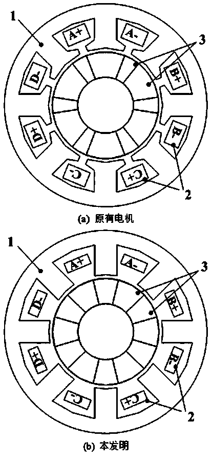
[0030] Taking the 4-phase, 8-slot, 6-pole permanent magnet as an example, its structure diagram is shown in figure 1 , the present invention is made up of stator core 1, stator winding 2, rotor permanent magnet 3. Eight armature straight teeth are evenly distributed on the stator core 1, and a set of concentrated windings is wound on each armature tooth and forms a phase by itself. Pole arc coefficient of stator core 1 k s =0.5. The stator winding is wound on the mould, fixed with glue, and then transplanted into the stator slot. The filling rate of the winding slot is about 68%, which is 18% higher than before. The wound windings are potted with epoxy resin glue, image 3 This is the picture of the motor after potting.

[0031] There is an air gap between the stator 1 and the rotor permanent magnet 3, here the value is 1mm.

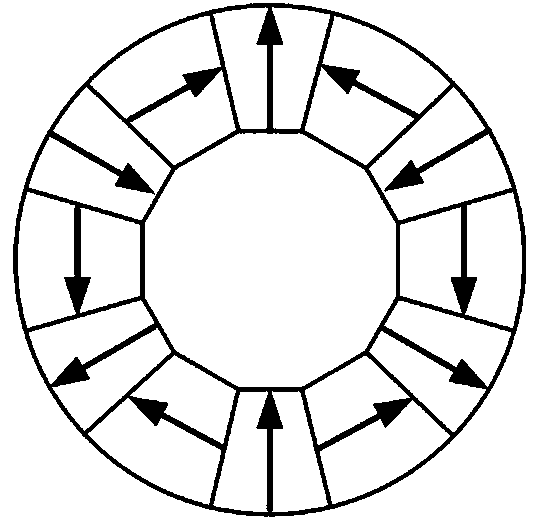
[0032] The number of poles of the rotor permanent magnet 3 is 6, and the permanent magnet pole arc coefficient of the radial magnetization directi...


PUM


Abstract

The invention discloses a high slot-fill factor high-performance permanent magnet motor with open slots and straight teeth, the motor including a stator and a rotor. The stator includes a stator core and stator windings. Stator teeth are made into straight teeth with equal tooth width and can be used for improving the slot-fill factor. As for the stator windings, single layer concentrated windings are employed, and each slot is wound by a winding. The rotor is composed of permanent magnets and a rotating shaft, and an air gap exists between the stator and the rotor. The permanent magnets are composed of permanent magnets arranged in a Halbach array, and are divided into radial permanent magnets and tangential permanent magnets according to different magnetizing directions, and each permanent magnet is of fan-shaped structure. The fan-shaped permanent magnets are arranged in an actinoid manner around an axial lead. The Halbach-type permanent magnet array can improve power density and reduce torque ripple. The motor provided by the invention is simple in structure, high in slot-fill factor, high in no-load back EMF sinusoidal degree, small in torque ripple and high in mechanical robustness, and is conducive to reducing positioning torque of the motor. In addition, physical isolation, thermal isolation and decoupling of a magnetic circuit are arranged between phases of the motor.

Description

technical field [0001] The invention relates to a high slot full rate and high performance open slot straight tooth permanent magnet synchronous motor, which can be used in aerospace and other fields that require high motor power density and reliability. Background technique [0002] In recent years, with the rapid development of rare earth permanent magnet materials, especially the continuous improvement of the performance of NdFeB permanent magnet materials and the gradual reduction of prices, permanent magnet motors have become more and more widely used in national defense, industrial and agricultural production, and household appliances. Applications. In some special fields such as aerospace and electric vehicles, motors are required to have high power density and efficiency. The slot fullness rate is the technical bottleneck for the improvement of motor efficiency and power density. [0003] Generally, permanent magnet synchronous motors often use distributed windings...

Claims


Application Information

Patent Timeline
Patent Type & Authority Applications(China)
IPC IPC(8): H02K21/14H02K1/16H02K1/22
Inventor 赵文祥雷倩朱纪洪吉敬华张新华
Owner JIANGSU UNIV
Why Eureka
Try Eureka