Image blur compensation device and imaging apparatus

a compensation device and image technology, applied in the field of image blur compensation technology, can solve the problems of increasing the size and power consumption of the apparatus, the difficulty of minimizing image blur, etc., and achieve the effect of suppressing image blur and simple configuration

Active Publication Date: 2014-02-04
CANON KK
View PDF8 Cites 5 Cited by
  • Summary
  • Abstract
  • Description
  • Claims
  • Application Information

AI Technical Summary

Benefits of technology

[0007]Accordingly, the present invention suppresses image blur caused by the displacement of the rotation center of the image sensor upon rotation of the image sensor without involving an increase in size of an apparatus in a simple configuration.
[0010]According to the present invention, an image blur caused by the displacement of the rotation center of the image sensor may be suppressed upon rotation of the image sensor without involving an increase in size of an apparatus in a simple configuration.

Problems solved by technology

In the conventional configuration, when the image sensor is rotated, it is difficult to minimize image blur by suppressing the displacement of the rotation center of the image sensor.
In other words, a drive unit having the second rotational force enough to conquer the decrease in the rotational force caused by the first rotational force is required, resulting in an increase in size and power consumption of an apparatus.

Method used


Image

  • Image blur compensation device and imaging apparatus
  • Image blur compensation device and imaging apparatus
  • Image blur compensation device and imaging apparatus

Examples


Embodiment Construction

[0019]Hereinafter, preferred embodiments of the present invention will be described with reference to the attached drawings.

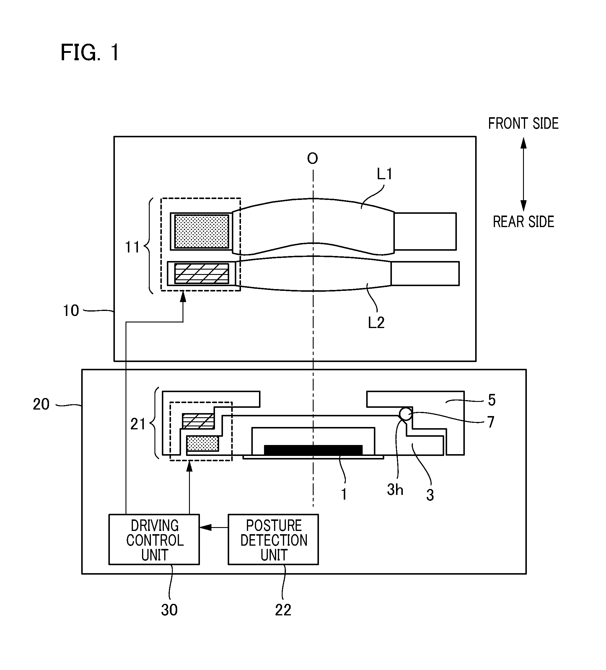
[0020]FIG. 1 is a schematic view illustrating an essential part of an imaging apparatus using an image blur compensation device according to the present embodiment. The image blur compensation device is a device that compensates image blur generated by the shake of the apparatus case. Hereinafter, a description will be given taking an example in which a digital still camera having a lens barrel 10 and a camera body 20 is used as an imaging apparatus.

[0021]The lens barrel 10 includes a first compensation unit 11. The first compensation unit 11 has a compensation lens L1 and a fixed lens L2, and performs the linear shifting movement of the compensation lens L1 in a plane perpendicular to the optical axis (see the axis “O” in FIG. 1) of the imaging apparatus. With this arrangement, image blur is compensated in the shift (linear) direction. Note that the lens barre...


PUM


Abstract

An image blur compensation device detects the shake of an apparatus and compensates image blur by means of a mechanism for rotating an image sensor about an axis perpendicular to the imaging plane of the image sensor. A rotary member for holding the image sensor is rotatably held by a base member. The rotary member and the base member are urged by a tension spring in a direction closer to each other, and a ball provided between the rotary member and the base member rotatably supports the rotary member in a state where the ball abuts against both the rotary member and the base member. The ball is arranged within a ball-receiving groove formed in the base member. The ball is brought into abutment against the abutment surface provided on the rotary member by an urging force of a tension spring.

Description

BACKGROUND OF THE INVENTION[0001]1. Field of the Invention[0002]The present invention relates to an image blur compensation technology that optically compensates image blur caused by an unintentional movement of hands.[0003]2. Description of the Related Art[0004]Conventionally, an image blur compensation device including a mechanism that moves some lenses (compensation lens) included in an imaging optical system or an image sensor in order to compensate image blur caused by an unintentional movement of hands during hand-held shooting is known. Image blur elimination control is performed by moving the compensation lens or the image sensor in a first direction and a second direction orthogonal to the first direction in a plane perpendicular to the optical axis of the imaging optical system.[0005]Japanese Patent Laid-Open No. 06-030327 discloses a device including a rotary mechanism which detects the inclination of a camera with the optical axis of the camera being as the rotation axis...

Claims


Application Information

Patent Timeline
Patent Type & Authority Patents(United States)
IPC IPC(8): H04N5/228
CPCH04N5/2328H04N23/685
Inventor MIYOSHI, KAORI
Owner CANON KK
Why Eureka
Try Eureka