Positioner

a technology of positioning device and positioner, which is applied in the direction of transducers, fluid pressure control, instruments, etc., can solve the problems of failure of the system, inability to know easily the actual operating mode of the positioner, and inability to control the opening

Inactive Publication Date: 2014-02-04
YAMATAKE HONEYWELL CO LTD
View PDF28 Cites 10 Cited by
  • Summary
  • Abstract
  • Description
  • Claims
  • Application Information

AI Technical Summary

Benefits of technology

[0010]The present invention is provided with positioner mode identifying means that identify the operating mode of the positioner as either the positive operating mode, wherein the greater the control output the greater the amplified pneumatic pressure signal, or the negative operating mode, wherein the greater the control output the less the amplified pneumatic pressure signal, making it possible to know easily the current operating mode of the positioner itself from the results of the identification by the positioner operating mode identifying means.

Problems solved by technology

However, in a conventional positioner it is not possible to know easily the actual operating mode of the positioner.
Because of this, if an operator is instructed to change the operating mode of a positioner but has forgotten to change the setting or makes an error in changing the setting, it may be set in the control valve without the error being discovered, and thus there is a risk that not only will the control of the opening not be performed correctly because the operating mode of the positioner does not match the operating mode of the control valve, but there is also the risk of producing a problem that causes a failure in the system wherein the flow of the fluid is controlled by the control valve.

Method used


Image

  • Positioner
  • Positioner
  • Positioner

Examples


Embodiment Construction

[0023]An example according to the present invention will be explained below in detail, based on the drawings

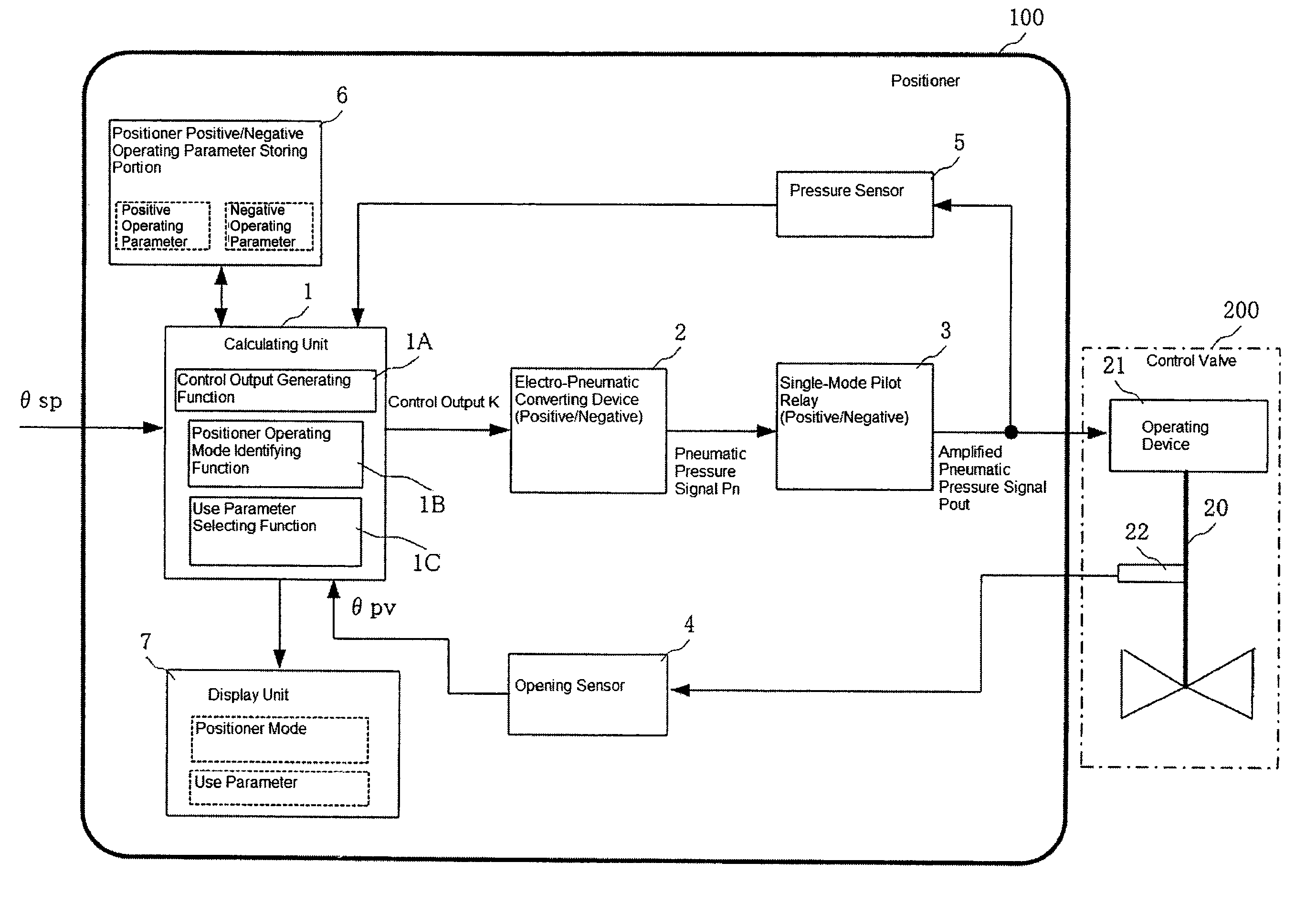
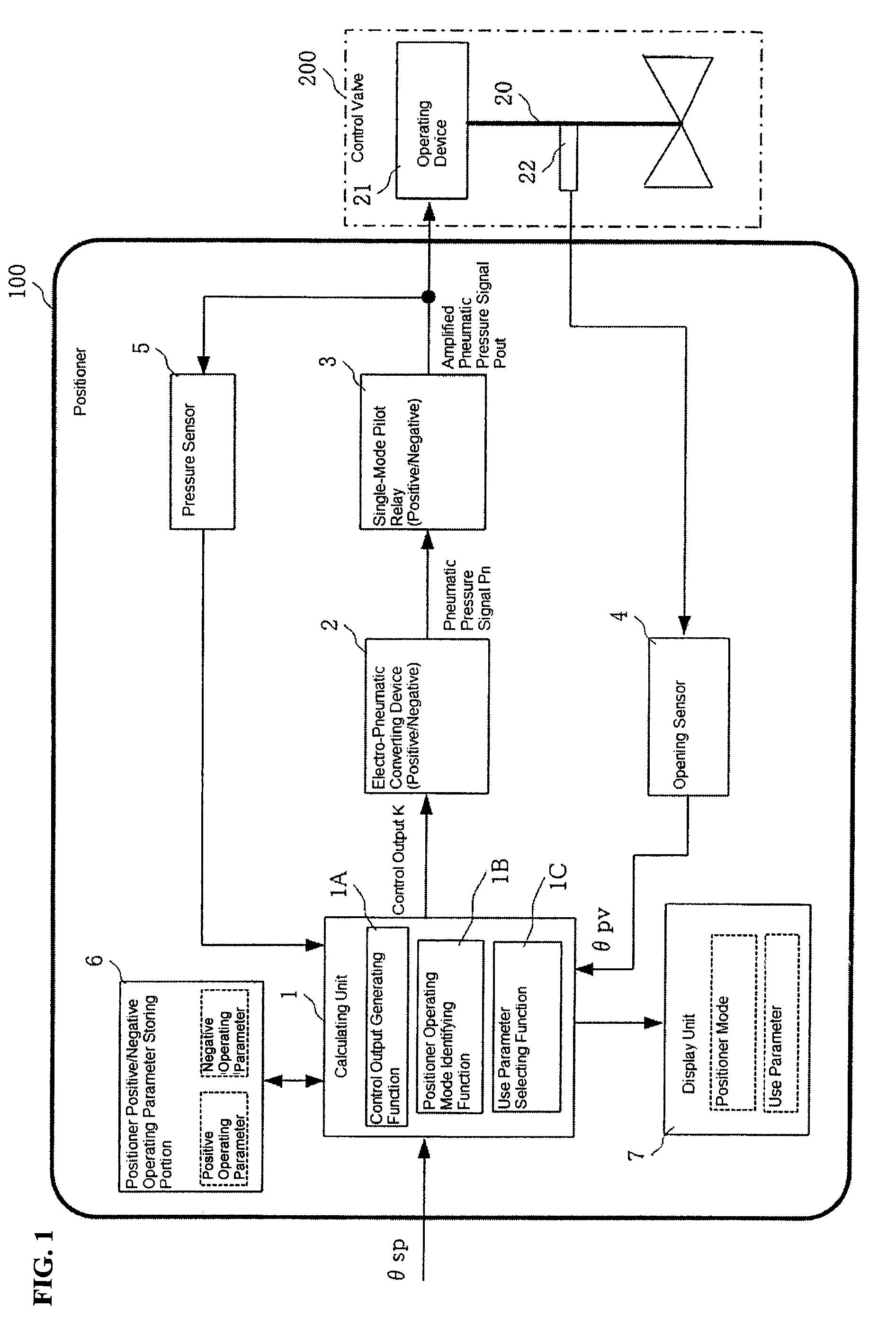
[0024]FIG. 1 is a block diagram illustrating an example of a positioner according to the present invention. In this figure, 100 is a positioner according to the present invention and 200 is a control valve wherein the opening thereof is adjusted by the positioner 100. The control valve 200 has an operating device 21 that drives a valve rod 20, and a feedback mechanism 22 that feeds back the amount of dislocation in the upward or downward direction at the valve rod 20.

[0025]The positioner 100 includes a calculating unit 1 for calculating a deviation between a valve opening setting value θsp, sent from a higher-level device (not shown), and an actual opening θpv, and back from the control valve 200, and for generating an electric signal, as a control output K, in accordance with this deviation; an electro-pneumatic converting device 2 for converting, into a pneumatic pressure si...


PUM


Abstract

A positioner operating mode identifying function is provided in a calculating unit. A pressure value of an amplified pneumatic pressure signal, from a single-mode pilot relay, is detected by a pressure sensor and sent to the calculating unit. The calculating unit, through the positioner operating mode identifying function, monitors a change in the amplified pneumatic pressure signal corresponding to a change in the control signal, and if the direction of change in the control output and the direction of change of the amplified pneumatic pressure signal are the identical direction, identifies the operating mode of the positioner as the positive operating mode. The operating mode of the positioner is identified as the negative operating mode if the direction of change in the control output and the direction of change of the amplified pneumatic pressure signal are the opposite directions. The identification results displayed on a screen of a display unit.

Description

CROSS REFERENCE TO RELATED APPLICATIONS[0001]The present application claims priority under 35 U.S.C. §119 to Japanese Patent Application No. 2010-079365, filed Mar. 30, 2010, which is incorporated herein by reference.FIELD OF TECHNOLOGY[0002]The present invention relates to a positioner for controlling the opening of a control valve by calculating a valve opening setting value sent from a higher-level device and an actual opening value fed back from the control valve that is being controlled, to generate, as a control output, an electric signal in accordance with the deviation, and then converting this generated control output into an air pressure signal, and then amplifying.BACKGROUND OF THE INVENTION[0003]Conventionally, positioners have been provided in control valves, where the valve opening of the control valve is controlled by the positioner. This positioner includes a calculating unit for calculating a deviation between a control valve opening setting value sent from a higher...

Claims


Application Information

Patent Timeline
Patent Type & Authority Patents(United States)
IPC IPC(8): G05D5/00F16K17/26G05D11/00G05D9/00G05D23/00G05D3/12F16K31/12F15B5/00
CPCF16K37/0066Y10T137/2452Y10T137/7761
Inventor INAGAKI, YOHSUKE
Owner YAMATAKE HONEYWELL CO LTD
Why Eureka
Try Eureka