Fire resistive joint cover system

a fire-resistive joint and cover technology, applied in resiliently-mounted floors, furniture, lighting and heating equipment, etc., can solve the problems that prior art fire-resistive joint cover systems often fail to adequately provide for joint movement or properly position fire-resistive materials within joints

Active Publication Date: 2014-02-11
BALCO
View PDF18 Cites 64 Cited by
  • Summary
  • Abstract
  • Description
  • Claims
  • Application Information

AI Technical Summary

Problems solved by technology

Unfortunately, prior art fire resistive joint cover systems often fail to adequately provide for joint movement or properly position fire resistive materials within joints.

Method used


Image

  • Fire resistive joint cover system
  • Fire resistive joint cover system
  • Fire resistive joint cover system

Examples


Embodiment Construction

[0026]The following detailed description of various embodiments of the invention references the accompanying drawings that illustrate specific embodiments in which the invention can be practiced. The embodiments are intended to describe aspects of the invention in sufficient detail to enable those skilled in the art to practice the invention. Other embodiments can be utilized and changes can be made without departing from the scope of the present invention. The following detailed description is, therefore, not to be taken in a limiting sense. The scope of the present invention is defined only by the appended claims, along with the full scope of equivalents to which such claims are entitled.

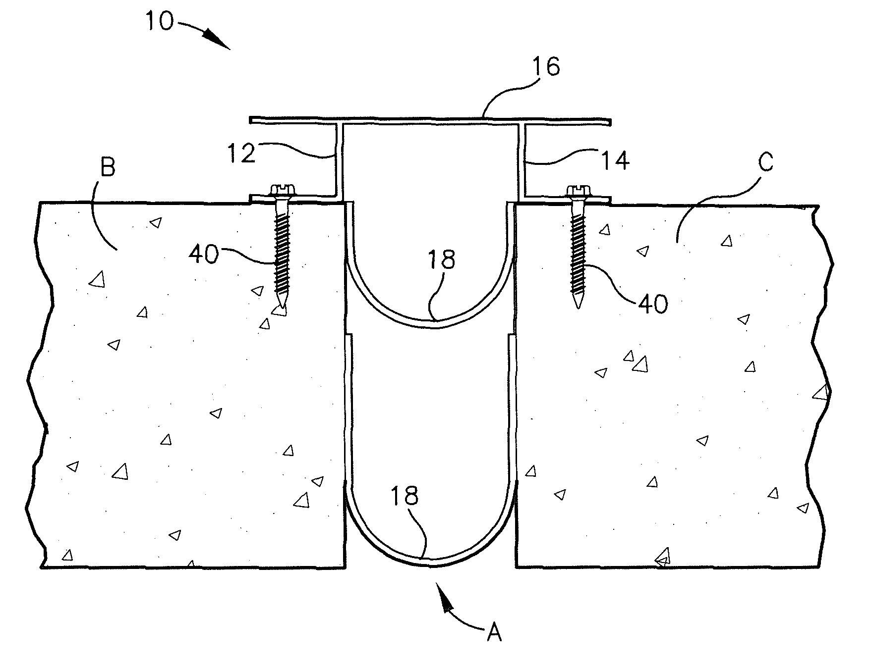
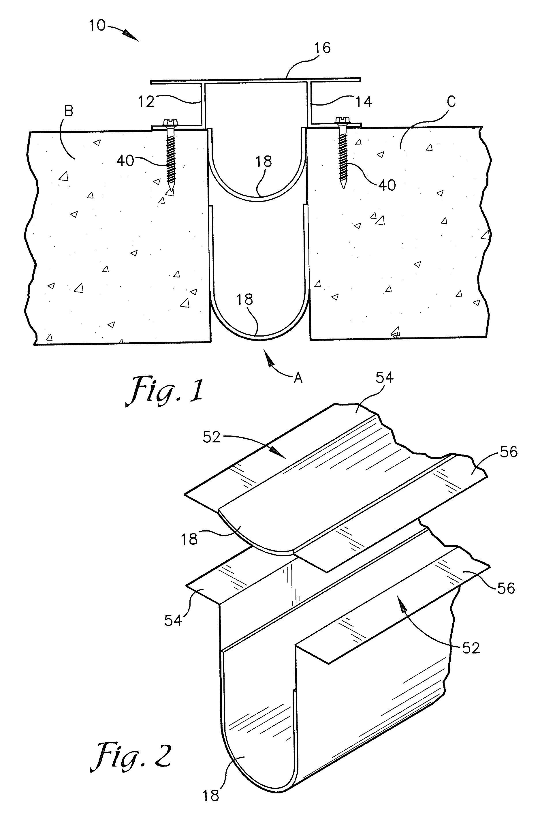
[0027]Referring to FIGS. 1-14, embodiments of the present invention provide a fire resistive joint cover system 10 operable to span a gap A between two surfaces B, C. The system 10 may be employed to span gaps between surfaces including roof, wall, floor, and ceiling members or any other gaps, joi...


PUM


Abstract

A fire resistive joint cover system operable to span a gap between two surfaces. The system generally may include first and second base members, a covering member, and an intumescent sheet. Each base member is operable to couple with one of the surfaces and the covering member is operable to couple with the base members to at least partially span the gap. In some embodiments, the covering member may be configured as a floating covering member and / or as a flexible elastomer seal.

Description

CROSS REFERENCE TO RELATED APPLICATION[0001]The present application is a continuation patent application and claims priority benefit, with regard to all common subject matter, of earlier-filed U.S. continuation patent application titled “FIRE RESISTIVE JOINT COVER SYSTEM”, Ser. No. 12 / 971,823, filed Dec. 17, 2010, which is a continuation patent application and claims priority benefit, with regard to all common subject matter, of earlier-filed U.S. nonprovisional patent application titled “FIRE RESISTIVE JOINT COVER SYSTEM”, Ser. No. 11 / 625,185, filed Jan. 19, 2007, now issued as U.S. Pat. No. 7,856,781, issued Dec. 28, 2010. The identified earlier-filed applications are hereby incorporated by reference in their entirety into the present application.BACKGROUND[0002]1. Field[0003]Embodiments of the present invention relate to fire resistive joint cover systems. More particularly, various embodiments of the invention provide a fire resistive joint cover system including at least one fi...

Claims


Application Information

Patent Timeline
Patent Type & Authority Patents(United States)
IPC IPC(8): E04B1/62
CPCE04B9/008E04F13/0889E04B5/023E04F15/02005E04B1/948E04B9/30
Inventor HILBURN, JR., JOHNNIE, DANIEL
Owner BALCO
Why Eureka
Try Eureka