Small planing boat

a small, planing boat technology, applied in the direction of special purpose vessels, vessel construction, power plants being motor-driven, etc., can solve the problems of over-revolution, faster abrasion and deterioration in the cylinders, and discomfort for riders, so as to achieve the desired durability and engine lifespan, improve operation comfort, and accelerate abrasion and deterioration.

Active Publication Date: 2014-02-11
YAMAHA MOTOR CO LTD
View PDF6 Cites 25 Cited by
  • Summary
  • Abstract
  • Description
  • Claims
  • Application Information

AI Technical Summary

Benefits of technology

[0009]As such, the cylinders scheduled to be deactivated later in the sequence are subject to the over-revolution state for longer periods. That is because when an over-revolution state is reached, and a phased deactivation process begins, the cylinders that are not deactivated first continue to operate even though the engine speed is above the predetermined speed. Thus, these cylinders are operated during the over-revolution state, and thereby power and thermal loads are unevenly distributed among the cylinders, which causes faster abrasion and deterioration in the cylinders that are scheduled to be deactivated later in the sequence. Therefore, to provide a desired durability and engine lifespan, the engine should be made thicker or larger in certain areas, which results in difficulties in fitting such an engine in the small engine compartments of small planing type watercraft.
[0011]Further, the center of gravity of outboard motor powered watercraft generally tends to be positioned toward the rear of the associated watercraft since the outboard motor is disposed at a rear end of the watercraft. Therefore, the rear part of the watercraft is usually positioned lower relative to the front part. The propeller, thus, is less likely to be exposed to the air for such a reason and thus the engine is less often subject to the over-revolution state.

Problems solved by technology

This tends to result in an over-revolution state and can cause discomfort for the riders.
That is because over-revolution states do not always last long enough for the controller to reach the end of the deactivation sequence.
Thus, these cylinders are operated during the over-revolution state, and thereby power and thermal loads are unevenly distributed among the cylinders, which causes faster abrasion and deterioration in the cylinders that are scheduled to be deactivated later in the sequence.
Therefore, to provide a desired durability and engine lifespan, the engine should be made thicker or larger in certain areas, which results in difficulties in fitting such an engine in the small engine compartments of small planing type watercraft.

Method used


Image

  • Small planing boat
  • Small planing boat
  • Small planing boat

Examples


Embodiment Construction

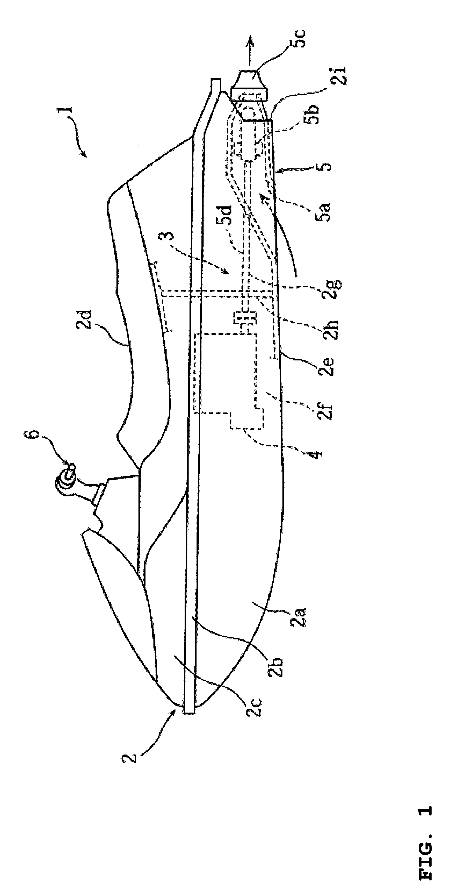
[0022]FIGS. 1 through 6 are drawings for describing a small planing boat 1 including a multi-cylinder engine in accordance with various embodiments. The various embodiments of the multi-cylinder engine are disclosed in the context of a small planing boat because it has particular utility in this context. However, the engines disclosed herein can be used in other contexts, such as, for example, but without limitation, engines of other vehicles including land vehicles and water vehicles.

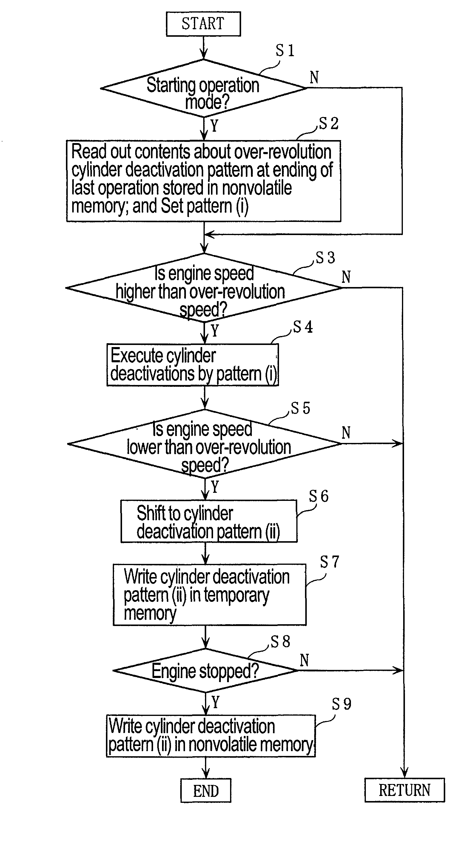
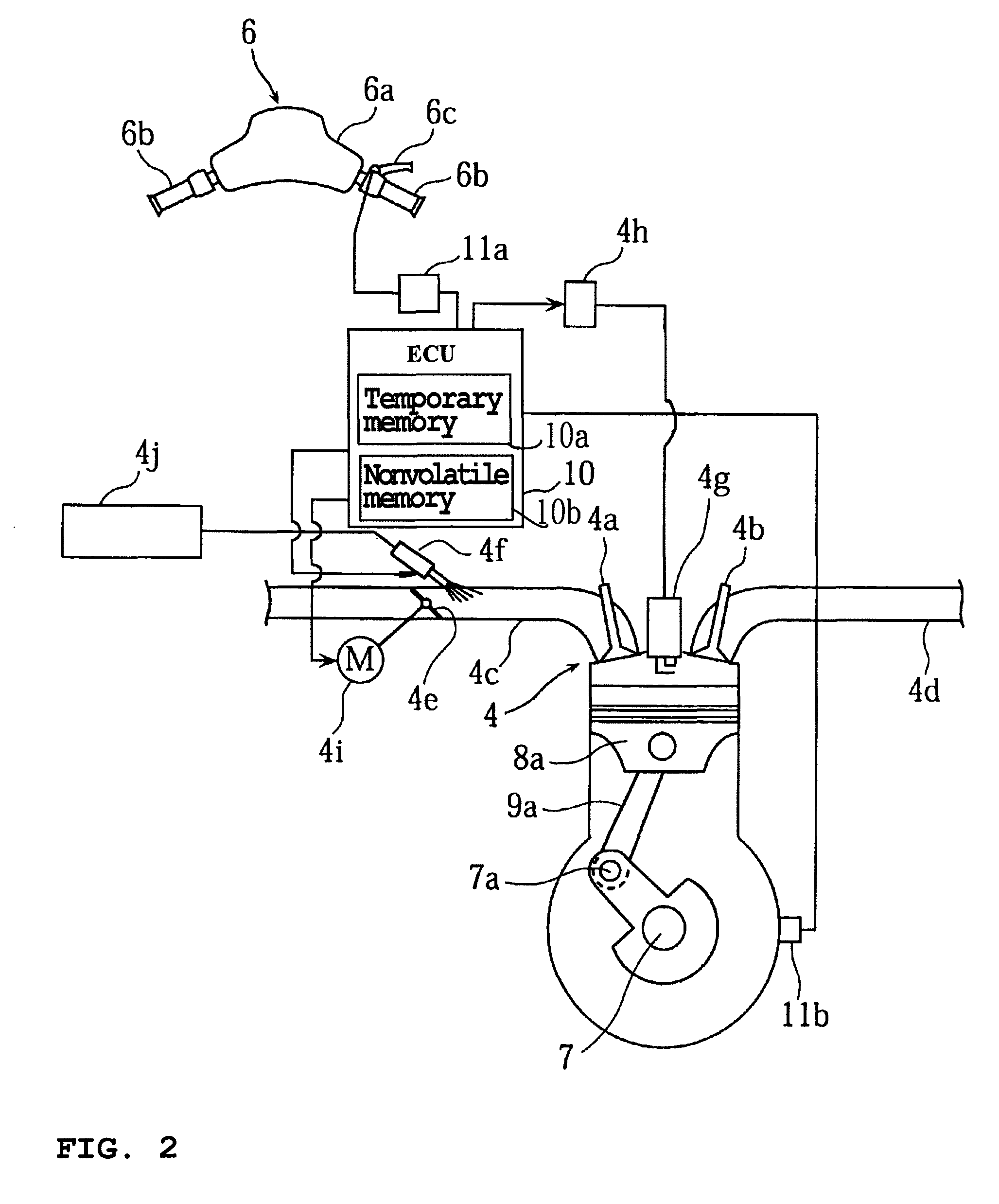
[0023]FIG. 1 is a side view of the small planing boat 1. FIG. 2 is schematic block diagram of an engine control device. FIG. 3 is a schematic view for describing cylinder dispositions and an ignition sequence. FIG. 4 is a chart showing cylinder deactivation sequence data. FIGS. 5 and 6 are flowcharts for explaining phased cylinder deactivations.

[0024]A hull 2 of the small planing boat 1 can be made of resin (FRP), or other materials. A lower hull portion 2a and an upper deck 2b can be tightly joined to...


PUM


Abstract

A small planing boat includes a multi-cylinder engine, and a propulsion unit driven by the engine for propelling a hull by drawing up and jetting out water. The engine can be configured to change the number of deactivated cylinders in a phased manner corresponding to an engine speed when the engine speed becomes a prescribed speed or more, and can include a memory for storing cylinder deactivation sequence schedules for determining sequences of cylinders that are deactivated and increasing the number of deactivated cylinders in a phased manner. An operation control device configured to deactivate the cylinders of the engine in a phased manner in accordance with the cylinder deactivation sequence schedules stored in the memory. The operation control device shifts the cylinder deactivation sequence schedules to be read out from the memory to another cylinder deactivation sequence schedule corresponding to an operational state of the engine.

Description

PRIORITY INFORMATION[0001]The present application is based on and claims priority under 35 U.S.C. §119(a-d) to Japanese Patent Application No. 2007-209864, filed on Aug. 10, 2007, Japanese Patent Application No. 2008-154058, filed on Jun. 12, 2008 and is a Continuation-in-Part of U.S. patent application Ser. No. 11 / 965,290 filed Dec. 27, 2007, the entire contents of all of which is expressly incorporated by reference herein.BACKGROUND OF THE INVENTIONS[0002]1. Field of the Inventions[0003]The present inventions relate to a small planing boats which have a multi-cylinder engines including operation control devices which change deactivated cylinders in a phased manner, for example, corresponding to an engine speed when the engine speed reaches or exceeds a predetermined speed.[0004]2. Description of the Related Art[0005]Small planing boats are frequently driven with their throttle valve at large openings and / or fully opened. During such operation, the engine speed can exceed the maxim...

Claims


Application Information

Patent Timeline
Patent Type & Authority Patents(United States)
IPC IPC(8): F02D13/06
CPCB63B35/731B63H21/14B63B34/10
Inventor KINOSHITA, YOSHIMASA
Owner YAMAHA MOTOR CO LTD
Why Eureka
Try Eureka